Spiral-flow type extraction and exhaust device with split structure

An exhaust device and split structure technology, which is applied in the field of swirling exhaust and exhaust devices, can solve problems such as difficult cleaning, reduced fan performance, and increased noise, and achieves the effects of easy cleaning, compact structure, and extended service life

Active Publication Date: 2012-04-11
UNIV OF SCI & TECH OF CHINA
View PDF3 Cites 7 Cited by
  • Summary
  • Abstract
  • Description
  • Claims
  • Application Information

AI Technical Summary

Problems solved by technology

Existing air extraction and exhaust systems often use the high-speed rotation of the fan impeller to generate negative pressure to achieve the effect of exhaust air. Whether it is an axial flow fan, a centrifugal fan or a diagonal flow fan, the fan impeller is in direct contact with the exhaust gas. There are many defects: 1. The blades of the fan are easy to stick to dirt, which destroys the balance of the blades and are difficult to clean. After a period of time, the performance of the fan decreases and the noise increases; 2. The blades of the fan block the pipeline. The power of the motor has a large energy consumption; 3. In the environment of corrosiveness and high temperature, the blades of the fan are easy to wear and tear, and the material requirements of the fan are high, but the service life is very short
When exhausting air indoors, if the exhaust gas is corrosive or high temperature, or contains solid particles, dust, liquid droplets and other pollutants, the fan may still be polluted

Method used


Image

  • Spiral-flow type extraction and exhaust device with split structure
  • Spiral-flow type extraction and exhaust device with split structure
  • Spiral-flow type extraction and exhaust device with split structure

Examples


Embodiment 1

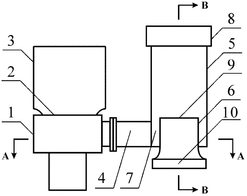
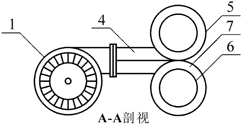
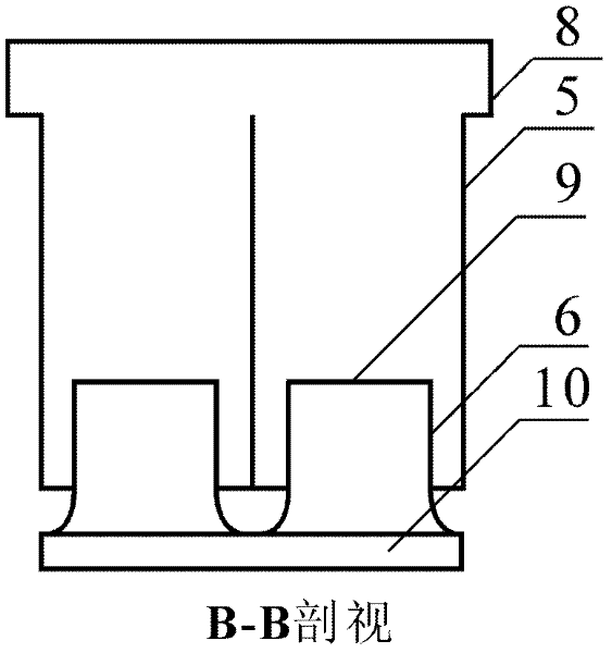
[0028] This embodiment is an implementation of a swirling air exhaust device with a split structure. figure 1 is a schematic diagram of its longitudinal section structure, figure 2 yes figure 1 The A-A cross-sectional structure schematic diagram of image 3 yes figure 1 Schematic diagram of the B-B cross-sectional structure.

[0029] Such as figure 1 , figure 2 and image 3As shown: In this embodiment, the air inlet 2 of the centrifugal fan 1 is connected with the air inlet pipe 3; there are two sets of swirl entrainment sleeves matching the fan 1, with the same shape and arranged side by side; the swirl entrainment sleeves The inner cylinder 6 with the central axis extends into the outer cylinder 5 to form an annular swirl groove 7 sealed at the bottom of the groove. The inner cylinder 6 and the outer cylinder 5 are straight-through circular pipes; The air supply duct 4 of the fan 1 is installed in a hole; the air supply duct 4 of the fan 1 is divided into two parts ...

Embodiment 2

[0033] This embodiment is another implementation of the swirling air exhaust device with split structure. figure 1 is a schematic diagram of its longitudinal section structure, Figure 4 yes figure 1 A-A cross-sectional schematic diagram of the structure.

[0034] Such as figure 1 and Figure 4 Shown: In this embodiment, only one set of swirl entrainment sleeves is used, and its structure is the same as that of Embodiment 1, the difference is that the air supply duct 4 of the fan 1 does not need to be divided again, and the centrifugal fan 1 is the same as that of the embodiment When 1 is the same, the geometric size of the swirl entrainment sleeve is 1.3 times larger than that of the single swirl entrainment sleeve in Example 1. When in use, start the centrifugal fan 1, draw clean air from the air inlet pipe 3 of the fan 1, and transport it to the annular swirl groove 7 of the swirl entrainment sleeve through the air supply pipe 4 of the fan 1, and the high-speed rotating...


PUM


Abstract

The invention provides a spiral-flow type extraction and exhaust device with a split structure, which comprises a fan and a spiral-flow entrainment sleeve that are combining. One group of spiral-flow entrainment sleeve can be used, and a combination structure of two or more spiral-flow entrainment sleeves can be simultaneously used. The spiral-flow entrainment sleeve forms an annular spiral-flow groove with a sealed groove bottom by extending inner cylinders with center shafts into an outer cylinder, a fan is positioned on the outer side of the spiral-flow groove, and an air delivery pipelineof the fan is communicated with the annular spiral-flow groove tangentially. The fan is used for extracting clean air for supply, the spiral-flow entrainment sleeve forms a strong negative pressure for exhausting and extracting air, an exhaust pipeline is smooth without blocking, and spiral flow has functions of centrifugal separation and filtration. The spiral-flow type extraction and exhaust device ensures that the fan is protected and the extraction and exhaust efficiency is high, achieves the purpose of efficiently saving energy because the fan and the spiral-flow entrainment sleeve are respectively used for extracting and exhausting air, and is especially suitable for indoor extraction and exhaust in various fields and delivery and treatment of corrosive or high-temperature gases.

Description

technical field [0001] The invention belongs to the technical field of pneumatic dedusting devices, in particular relates to the transport and treatment of indoor exhaust air and corrosive or high-temperature gas, and particularly relates to a swirling air exhaust device with split structure. Background technique [0002] In order to prevent harmful substances from polluting the indoor air environment and affecting human health, the exhaust system is widely used in production workshops, warehouses, supermarkets, food processing plants, chemical plants, hotels, hotels, subway stations, stadiums, mines, tunnels, underground areas such as garages. Existing air extraction and exhaust systems often use the high-speed rotation of the fan impeller to generate negative pressure to achieve the effect of exhaust air. Whether it is an axial flow fan, a centrifugal fan or a diagonal flow fan, the fan impeller is in direct contact with the exhaust gas. There are many defects: 1. The bla...

Claims


Application Information

Patent Timeline
Patent Type & Authority Applications(China)
IPC IPC(8): F24F7/007
Inventor 司廷
Owner UNIV OF SCI & TECH OF CHINA
Why Eureka
Try Eureka