Optical system, optical apparatus equipped therewith, and method for manufacturing optical system
一种光学系统、光焦度的技术,应用在光学系统领域,能够解决像差校正不充分等问题,达到优良光学性能的效果
- Summary
- Abstract
- Description
- Claims
- Application Information
AI Technical Summary
Problems solved by technology
Method used
Image

Examples
no. 1 example
[0069] An optical system according to a first embodiment of the present application is explained below.
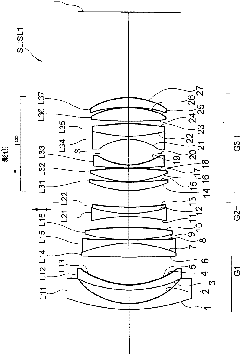
[0070] The optical system according to the first embodiment of the present application includes, in order from the object side, a first lens group, a second lens group having negative refractive power, and a third lens group having positive refractive power. The second lens group is movable in a direction including a component perpendicular to the optical axis. This optical system satisfies the following conditional expression (1):
[0071] 0.30
[0072] Here f represents the focal length of the optical system when focusing on an object at infinity, and f23 represents the combined focal length of the second lens group and the third lens group when focusing on an object at infinity.
[0073] In a short focal length lens, in order to secure a back focus distance sufficient for a single-lens reflex camera and a digital camera, it has been known that it is eff...
no. 2 example
[0142] Then, an optical system according to a second embodiment of the present application is explained below. An optical system according to a second embodiment includes a first lens group; a lens having a negative refraction that is placed on the image side of the first lens group and is movably placed in a direction including a component perpendicular to the optical axis power of the second lens group; a third lens group having positive refractive power placed on the image side of the second lens group; and an aperture stop placed on the image side of the second lens group . The second lens group includes a positive lens having a convex surface facing the object side.
[0143] In the optical system according to the second embodiment of the present application, by disposing the vibration reduction lens group which is the second lens group on the image side of the first lens group, it becomes possible to realize excellent aberration correction.
[0144] When performing vibr...
no. 3 example
[0211] Then, a third embodiment according to the present application is explained below. An optical system according to a third embodiment of the present application includes, in order from the object side, a first lens group, a second lens group having negative refractive power, and a third lens group having positive refractive power. The second lens group is a vibration reduction lens group that moves in a direction including a component perpendicular to the optical axis, thereby moving an image.
[0212] Also, the optical system according to the third embodiment of the present application satisfies the following conditional expression (8):
[0213] 2.00<∑dvr / f<5.00 (8)
[0214] Here Σdvr represents the distance between the most image-side lens surface of the second lens group and the paraxial focal plane of the optical system when focusing on an object at infinity, and f represents the entire optical system when focusing on an object at infinity focal length.
[0215] In...
PUM
 Abstract
Description
Claims
Application Information
 - R&D
- Intellectual Property
- Life Sciences
- Materials
- Tech Scout
- Unparalleled Data Quality
- Higher Quality Content
- 60% Fewer Hallucinations
Browse by: Latest US Patents, China's latest patents, Technical Efficacy Thesaurus, Application Domain, Technology Topic, Popular Technical Reports.
© 2025 PatSnap. All rights reserved.Legal|Privacy policy|Modern Slavery Act Transparency Statement|Sitemap|About US| Contact US: help@patsnap.com