Clamping block of lead clamping device

A technology of wire clamps and clamping blocks, which is applied in the installation of cable installation devices, electrical components, cables, etc., can solve the problems of wire clamps slipping, wire clamps falling off, and wire clamps slipping, etc., so as to reduce wire damage , the effect of increasing the friction area

Inactive Publication Date: 2012-04-11
李刚
View PDF3 Cites 5 Cited by
  • Summary
  • Abstract
  • Description
  • Claims
  • Application Information

AI Technical Summary

Problems solved by technology

Even so, it has not fundamentally solved the problem of the wire clamp slipping during the wire laying process. When the wire clamp slips, the wire clamp will fall off from the end of the wire, and the serious consequences of tower destruction will be caused.
[0003] The key reason why the existing wire gripper slips during the movement of the wire is that: becau

Method used


Image

  • Clamping block of lead clamping device
  • Clamping block of lead clamping device
  • Clamping block of lead clamping device

Examples


Example Embodiment

[0013] The present invention will be further described below in conjunction with the drawings.

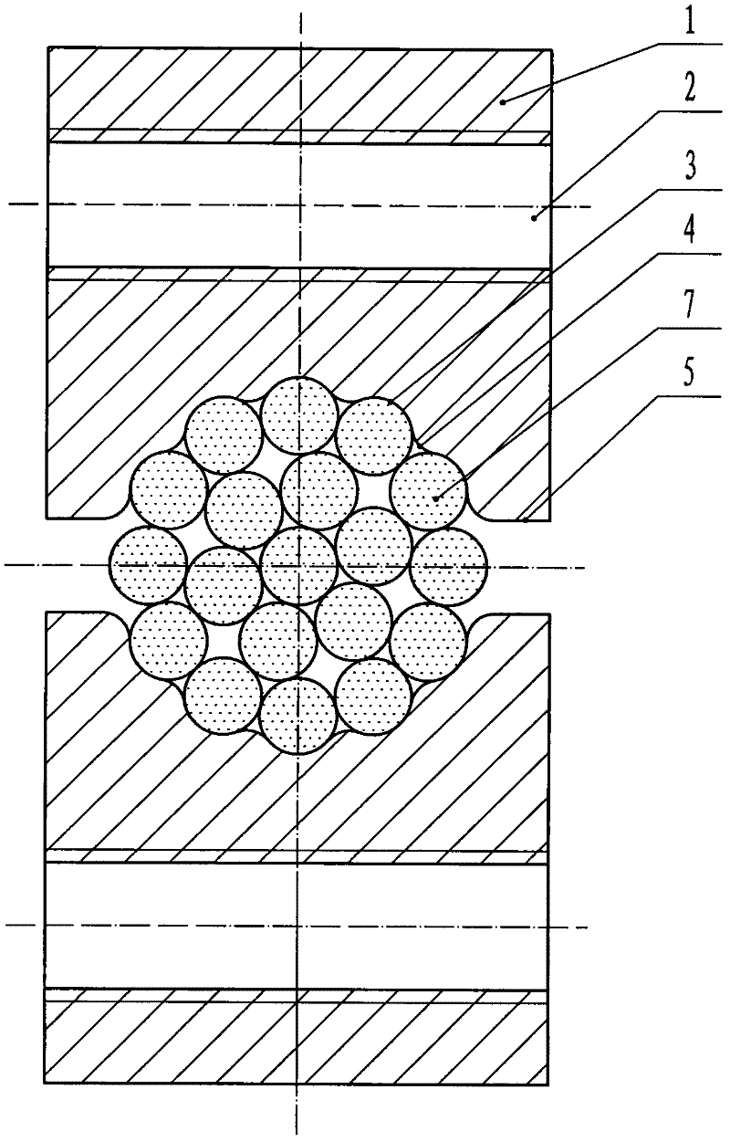
[0014] Such as Figure 1 ~ Figure 4 As shown, two pieces of the wire clamp block of the present invention are symmetrically arranged when in use, and the two pieces have the same structure. Each wire clamp block is an integral piece, and is on a plane along the length direction of the wire clamp block body 1 A wire clamping groove 6 is provided, and the shape of each wire clamping block body 1 is an approximate cuboid.
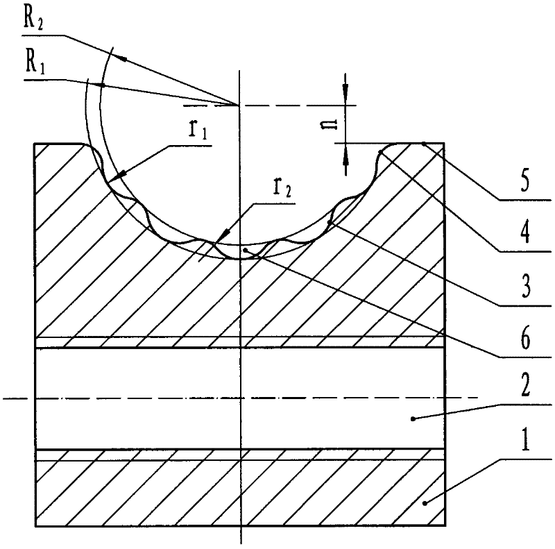
[0015] Such as figure 2 As shown, the cross-section of the card slot 6 is a radius r 1 The card wire arc surface 3 equal to the radius of the single strand aluminum wire of the outer ring of the wire 7 and the radius r 2 The arc vertices of the card line arc 3 and the intermediate transition arc 4 are respectively distributed in the radius R 1 And half warp R 2 On the arc, the card line arc 3 and the transition arc 4 are tangent to form a wavy groove arc, R 1 Equal to ...


PUM


Abstract

The invention discloses a clamping block of a lead clamping device for the lead clamping device. When the lead clamping device is used, two clamping blocks of the same structure are arranged symmetrically, and the clamping blocks can not slide in lead clamping; each clamping block comprises a lead clamping arc surface, a transition arc surface, a plane at the port of a lead clamping groove and threaded connection holes, wherein the clamping block body is approximate to be cuboid; a multi-head helical lead clamping groove is processed on a plane of the clamping block body along the length direction; the space, the turning direction and the lead angle of the lead clamping groove are the same as those of each strand aluminum lead of an lead outer ring; the cross section of the lead clamping groove is a wave-shaped arc cross section which is formed by a plurality of lead clamping arc surfaces the radius r1 of each of which equals to the radius of the single strand aluminum lead of the lead outer ring and a plurality of transition arc surfaces with the radius r2, wherein the lead clamping arc surfaces are tangent with the transition arc surfaces; the transition arc surfaces at two sides are respectively tangent with the plane at the port of the lead clamping groove; and the threaded connection holes are arranged at the two planes which are adjacent to the plane for the lead clamping groove along the length direction of each clamping block.

Description

technical field [0001] The invention belongs to an accessory of a small appliance in the construction of electric power lines, and in particular relates to a clamping block for a wire clamping device. The wires mentioned here are aluminum stranded wires or steel-cored aluminum stranded wires used on high-voltage transmission lines. The whole bare wire wound with a certain helix angle. Background technique [0002] The wire clamp is an essential device in the construction of power lines. It is a device used to clamp the end of the wire so as to pull it during the process of laying out the wire. The wire clamping device mostly adopts a four-bar linkage mechanism, so that the two clamping chuck main bodies whose upper and lower wire clamping grooves are parallel to each other move towards each other, and the wire is clamped through the clamping grooves on the wire clamping chuck main body. Due to the different hardness and strength required by the clamping groove of the clamp...

Claims


Application Information

Patent Timeline
IPC IPC(8): H02G1/00
Inventor 李刚甘文辉
Owner 李刚
Why Eureka
Try Eureka