
Electric mechanical interlocking type two-incoming-line and one-bus-couple system

A technology of electrical machinery and interconnection systems, applied in the direction of electrical components, circuits, electrical switches, etc., can solve the problems of inability to realize automatic power conversion, long power failure time, and large economic losses, so as to avoid accidents caused by reverse power transmission and replace The effect of low cost and short lead time

Active Publication Date: 2013-10-23
ZHUHAI FENGLAN INDAL
View PDF6 Cites 0 Cited by
  • Summary
  • Abstract
  • Description
  • Claims
  • Application Information

AI Technical Summary

Problems solved by technology

[0002] At present, the two-inlet-one bus-tie system used in the market is often due to the space limitation of the power distribution room. The two high-capacity transformer incoming line switches are arranged in a row respectively. Due to the distance between the two incoming line switches, they are either controlled by logic such as PLC. Relays realize electrical interlocking and automatic switching of the power system; or purely manual control switching, using key locks to achieve only mechanical interlocking
The former uses relays to achieve electrical interlocking, but because there is no mechanical interlocking, the system is unreliable, and electrical failures can lead to reverse power transmission and injury accidents; the latter is due to purely mechanical interlocking. Breaking one line of incoming line switch and then connecting the bus tie switch can not realize fast and correct automatic power conversion, which may lead to long power outage, huge economic losses, or major accidents caused by misoperation due to human paralysis

Method used


Image

  • Electric mechanical interlocking type two-incoming-line and one-bus-couple system
  • Electric mechanical interlocking type two-incoming-line and one-bus-couple system
  • Electric mechanical interlocking type two-incoming-line and one-bus-couple system

Examples


Embodiment Construction

[0039] In order to fully understand the technical content of the present invention, the technical solutions of the present invention will be further introduced and illustrated below in conjunction with specific examples, but not limited thereto.

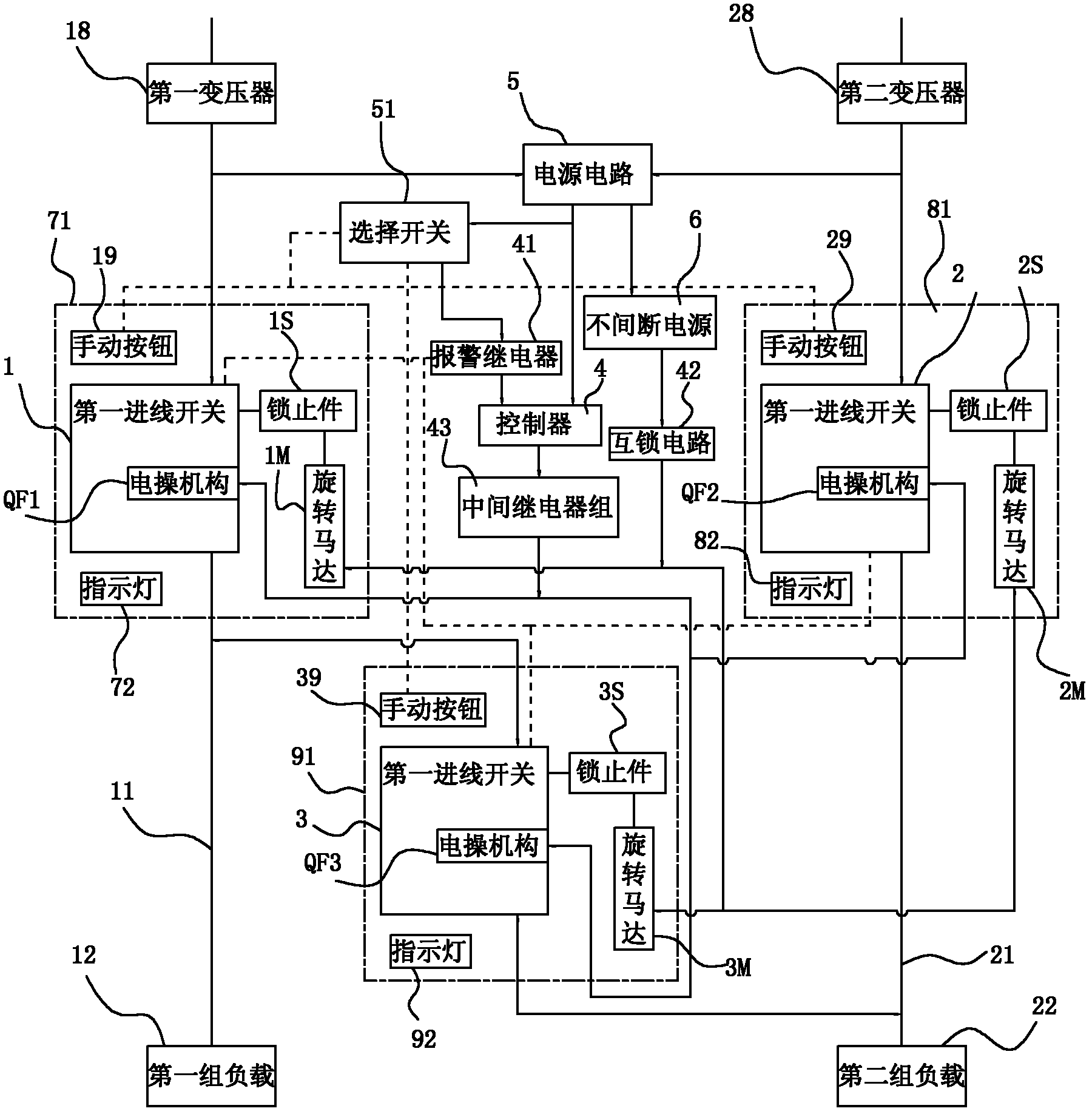
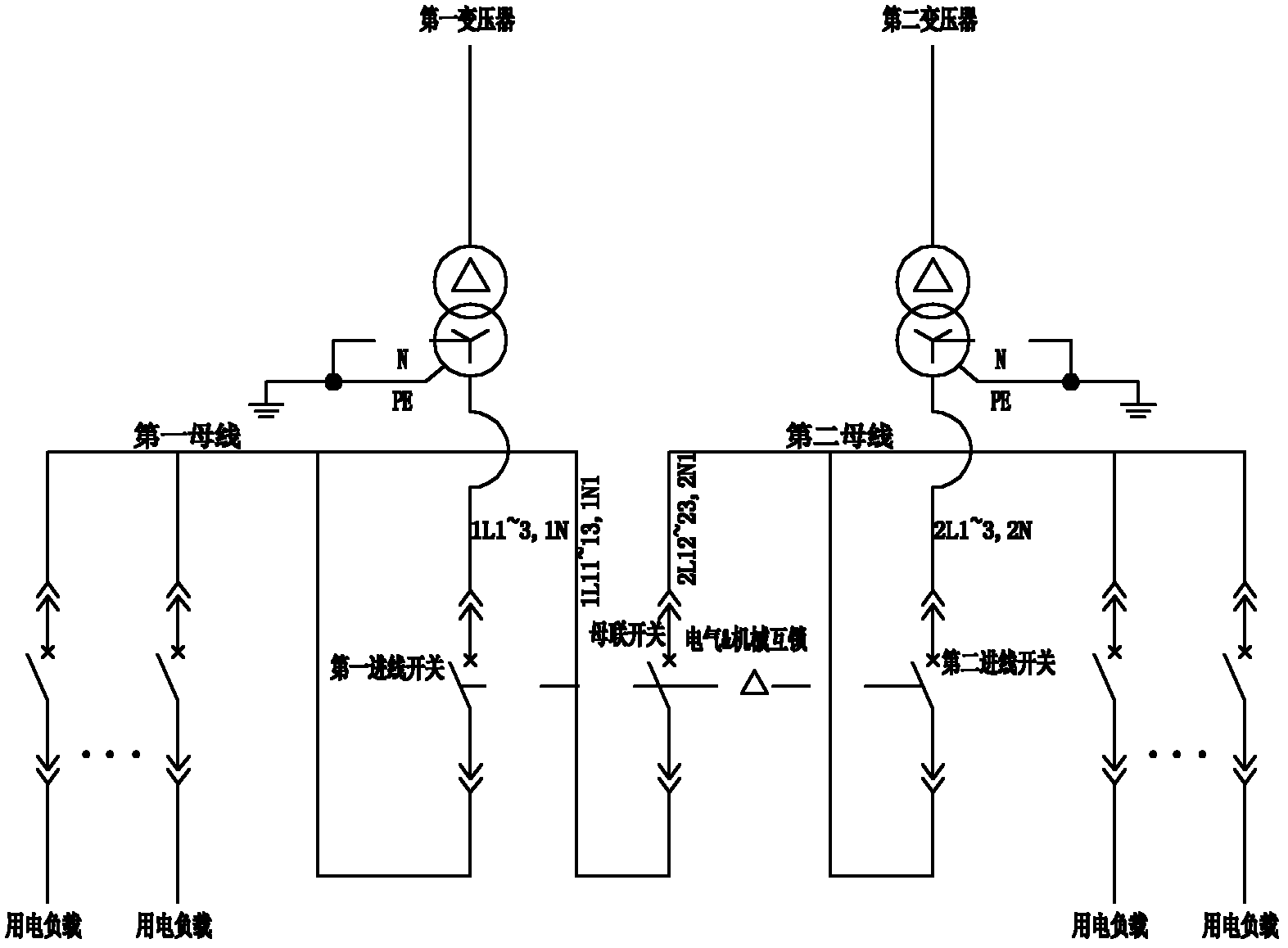
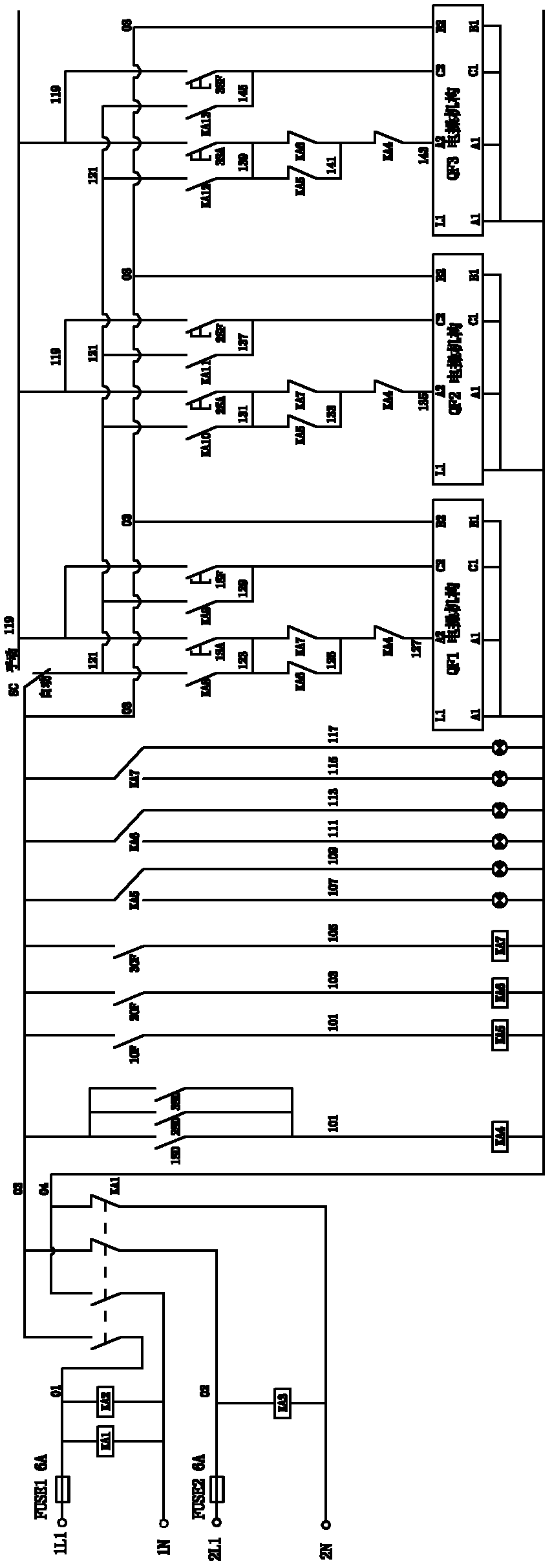
[0040] Such as Figure 1 to Figure 7 As shown, the electrical mechanical interlocking two-inlet-one bus tie system of the present invention includes a first incoming line switch 1 connected to the first power incoming line, a second incoming line switch 2 connected to the second power incoming line, and a first incoming line switch 2 connected to the second electric power incoming line. The incoming line switch 1 is connected to the first group of loads 12 through the provided first bus bar 11, and the second incoming line switch 2 is connected to the second group of loads 22 through the provided second bus bar 21, and also includes a connection for connecting the first group of loads. The bus tie switch 3 of the bus bar 11 and the s...


PUM


Abstract

The invention discloses an electric mechanical interlocking type two-incoming-line and one-bus-couple system. The system provided by the invention comprises a first incoming breaker which is connected with a first power supply incoming line and a second incoming breaker which is connected with a second power supply incoming line; the first incoming breaker is connected with a first group of load through a first bus and the second incoming breaker is connected with a second group of the load through a second bus; the system further comprises a bus couple switch which is used for connecting the first bus with the second bus; the first incoming breaker, the second incoming breaker and the bus couple switch are all provided with switch contact sets and electric operation mechanisms for driving the switch contact sets to switch on / off; the system further comprises a controller which is electrically connected with the electric operation mechanisms and further comprises a power supply circuit which is electrically connected with the controller. According to the invention, the system is not limited by an installation position and the mechanical interlocking can be realized; the power supply switching can be reliably realized and wounding accidents caused by reverse power transmission can be avoided; when the mechanical interlocking is installed, the automatic and rapid power supply switching can be realized by adopting a PLC (Programmable Logic Controller) logic control relay, so that the labor power for judging and operating can be saved and the accidents caused by the incorrect manipulation can be avoided.

Description

technical field [0001] The invention relates to a power supply control system, more specifically a two-inlet and one bus-tie power supply system, which realizes the interlocking of two incoming line switches and one bus-tie switch through the combination of electricity and machinery. Background technique [0002] At present, the two-inlet and one-bustie system used in the market is often due to the space limitation of the power distribution room. The two high-capacity transformer incoming line switches are arranged in a row respectively. Due to the distance between the two incoming line switches, they are either controlled by logic such as PLC. Relays realize electrical interlocking and automatic switching of the power system; or purely manual control switching, using key locks to achieve only mechanical interlocking. The former uses relays to achieve electrical interlocking, but because there is no mechanical interlocking, the system is unreliable, and electrical failures c...

Claims


Application Information

Patent Timeline
Patent Type & Authority Patents(China)
IPC IPC(8): H02J9/06H01H9/26
Inventor 方小幺肖辉涛彭泽奇李小平
Owner ZHUHAI FENGLAN INDAL
Learn More