Check patentability & draft patents in minutes with Patsnap Eureka AI!

Programmable exception processing latency

A technology of waiting time and exception handling, which is applied in the fields of electrical digital data processing, climate sustainability, instruments, etc., and can solve problems such as user restrictions

Active Publication Date: 2012-04-11
MICROCHIP TECH INC
View PDF6 Cites 1 Cited by
  • Summary
  • Abstract
  • Description
  • Claims
  • Application Information

AI Technical Summary

Problems solved by technology

This can be very restrictive for users

Method used


Image

  • Programmable exception processing latency
  • Programmable exception processing latency
  • Programmable exception processing latency

Examples


Embodiment Construction

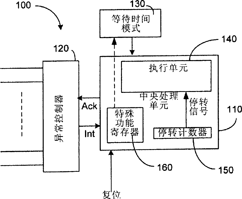
[0020] According to the teachings of the present invention, it is possible to design a processor that operates in at least two modes, where the first mode provides a fixed latency, where all exceptions have the same latency. A second mode may be set in which the processor has a variable latency depending on the pending instruction during which the exception occurred. An exception may be any type of external or internal interrupt or trap caused within a processing unit. A pending instruction is understood to be an instruction that must be executed before an exception can be handled. In many processor architectures, this instruction is the instruction executed in the loop following the loop during which the exception occurred. However, depending on the embodiment, it could also be an instruction that was pending when the interrupt occurred. A control register may be used that provides, for example, a bit to select the first or second mode. However, other means to signal a par...


PUM


Abstract

A digital processor with programmable exception processing latency, may have a central processing unit (CPU) of a digital processor, an exception controller coupled with said CPU, and a control register coupled with said CPU, wherein the control register is operable to set the operation mode of said CPU in at least one of two modes, wherein in the first mode the CPU has a fixed exception processing latency time, and in a second mode the CPU has a variable exception processing latency time.

Description

[0001] Related Application Cross Reference [0002] This application claims the benefit of U.S. Provisional Application No. 61 / 226,924, filed July 20, 2009, and entitled "PROGRAMMABLE EXCEPTION PROCESSING LATENCY," which is incorporated in its entirety. into this article. technical field [0003] The present invention relates to digital processors, and more particularly to exception latencies in digital processors. Background technique [0004] Digital processors typically operate synchronously with a processing clock by executing instructions sequentially stored in a program memory. However, these processors must be interfaced with external devices. One type of interfacing is performed by so-called interrupts. This event interrupts the sequential execution of the program and forces the processor into an exceptional state in which it executes a so-called interrupt service routine. During this service routine, external events are processed. In contrast to the synchronou...

Claims


Application Information

Patent Timeline
Patent Type & Authority Applications(China)
IPC IPC(8): G06F13/24
CPCG06F13/24G06F13/1668Y02D10/00
Inventor 迈克尔·I·卡瑟伍德戴维·米基
Owner MICROCHIP TECH INC
Features
  • R&D
  • Intellectual Property
  • Life Sciences
  • Materials
  • Tech Scout
  • Unparalleled Data Quality
  • Higher Quality Content
  • 60% Fewer Hallucinations
Learn More