Method and system for congestion control in a fibre channel switch

a fibre channel switch and congestion control technology, applied in data switching networks, frequency-division multiplexes, instruments, etc., can solve problems such as congestion in the overall system, fibre channel switches and standard do not provide a mechanism wher

Inactive Publication Date: 2005-01-27
MARVELL ASIA PTE LTD
View PDF99 Cites 71 Cited by
  • Summary
  • Abstract
  • Description
  • Claims
  • Application Information

AI Technical Summary

Benefits of technology

[0042] The switch element further includes logic for generating a credit limiting signal to set a control bit value that enables the credit limiting feature; a blocking counter that maintains a count for a number of R-RDYs that are received after a frame has departed; and logic for comparing the blocking counter value with a second threshold value and generating a signal for blocking frame transmission from a particular source port based on the comparison.

Problems solved by technology

Hence port 204 will not be able to transmit at its bandwidth and cause congestion in the overall system.
The present fibre channel switches and standard do not provide a mechanism where “available credit” can be used for congestion control and for managing frame flow within a Fabric.

Method used


Image

  • Method and system for congestion control in a fibre channel switch
  • Method and system for congestion control in a fibre channel switch
  • Method and system for congestion control in a fibre channel switch

Examples


Embodiment Construction

[0055] Definitions:

[0056] The following definitions are provided as they are typically (but not exclusively) used in the fibre channel environment, implementing the various adaptive aspects of the present invention.

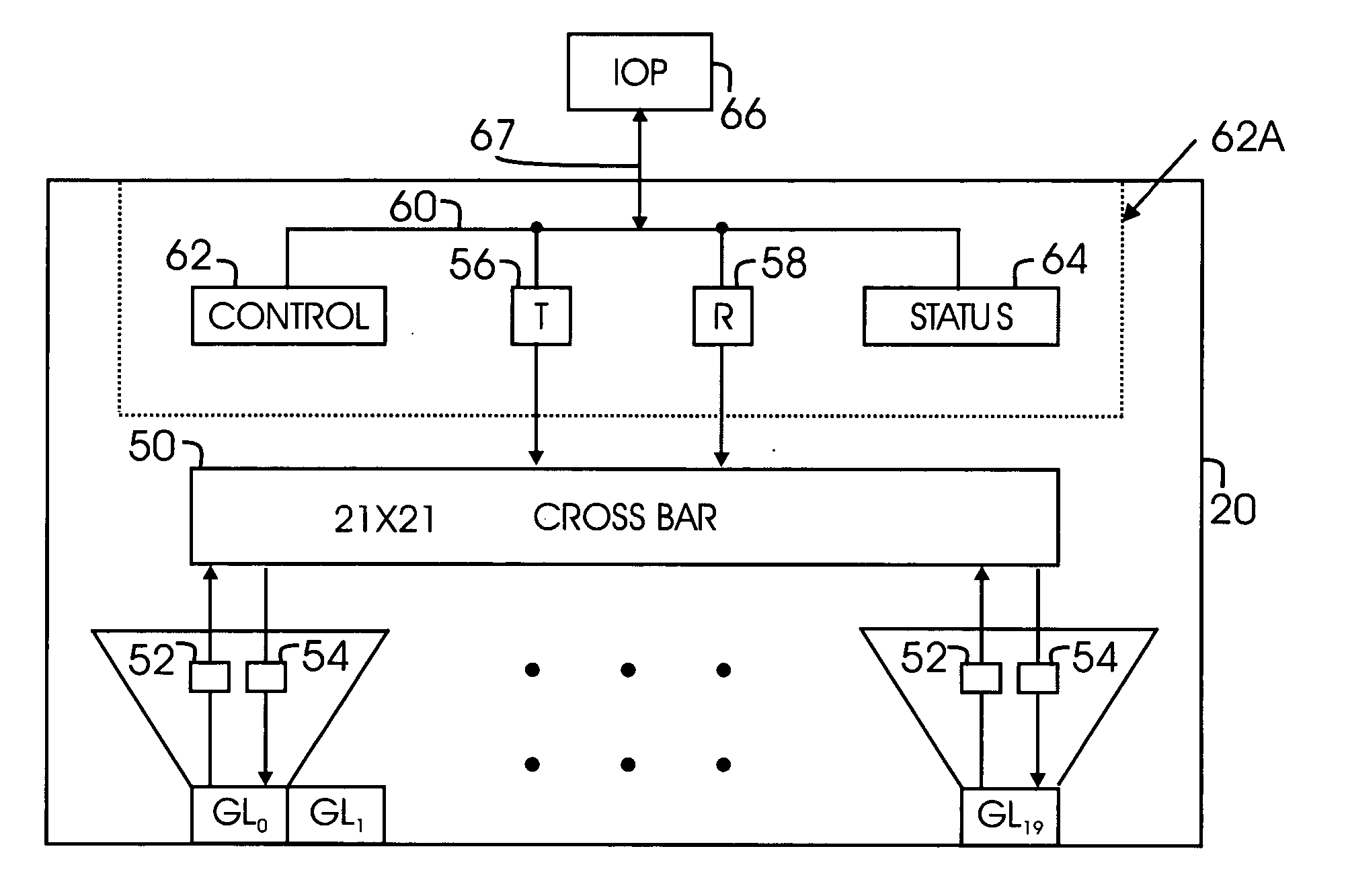
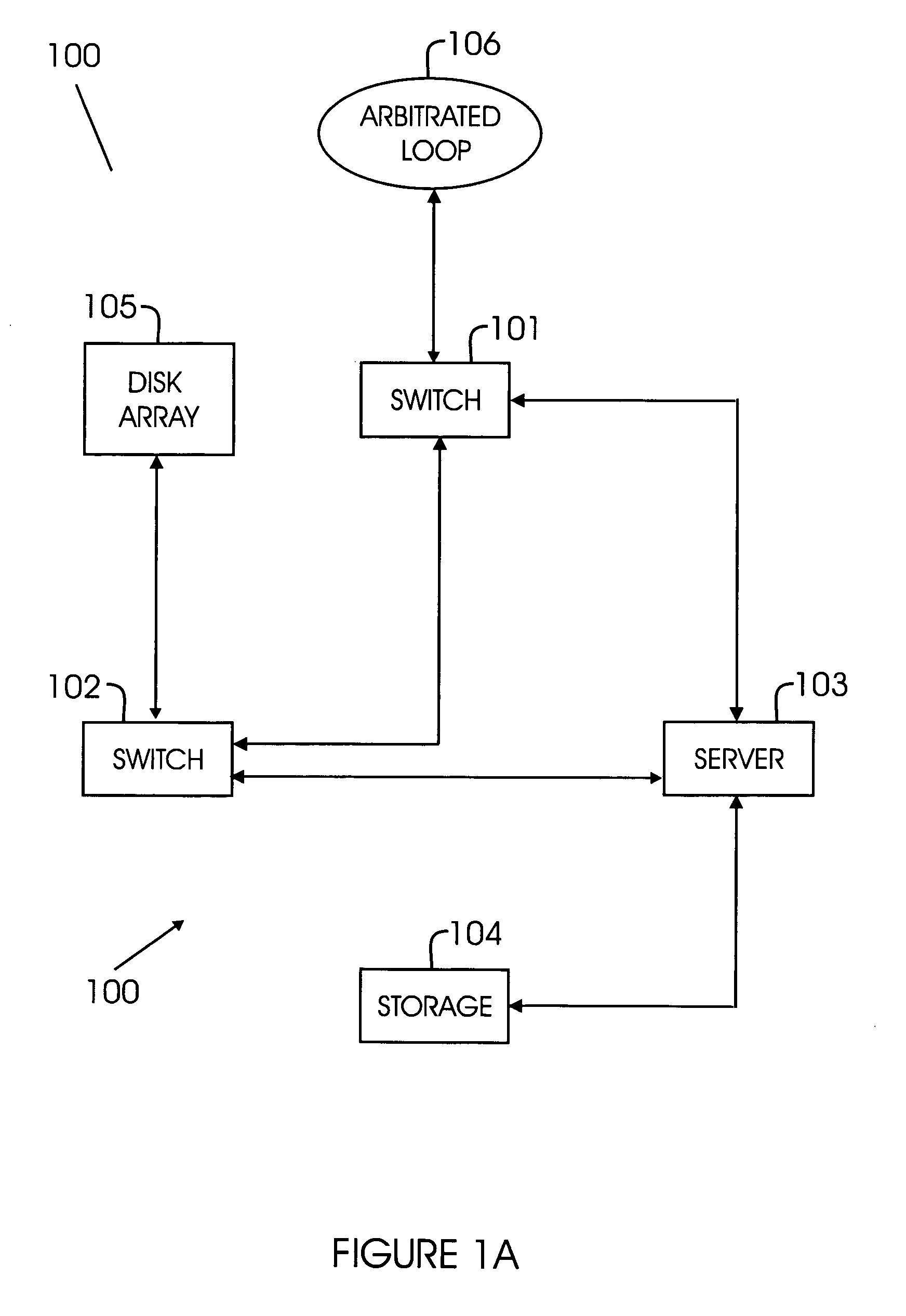
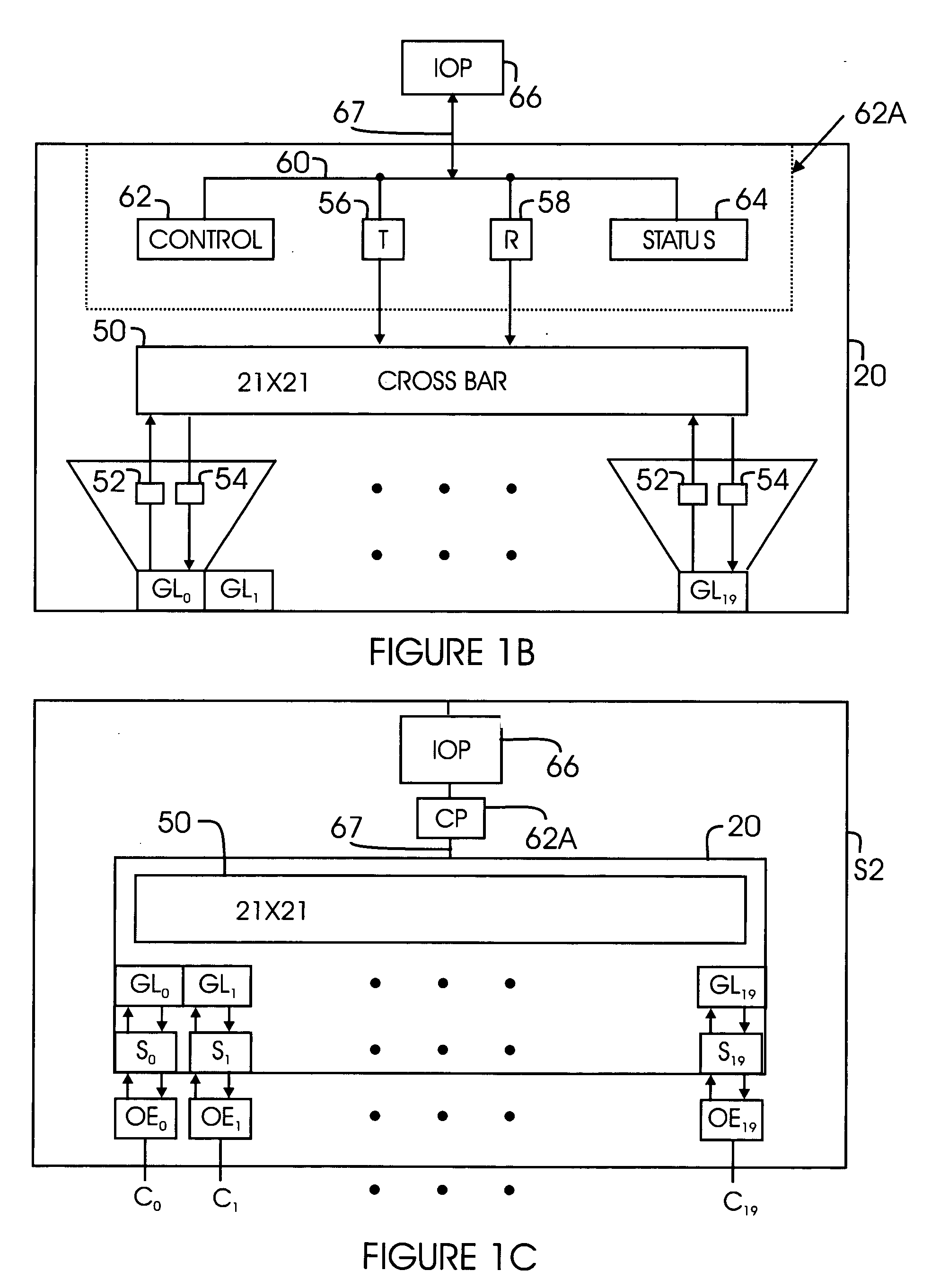
[0057]“E-Port”: A fabric expansion port that attaches to another Interconnect port to create an Inter-Switch Link.

[0058]“F_Port”: A port to which non-loop N_Ports are attached to a fabric and does not include FL_ports.

[0059]“Fibre channel ANSI Standard”: The standard, incorporated herein by reference in its entirety, describes the physical interface, transmission and signaling protocol of a high performance serial link for support of other high level protocols associated with IPI, SCSI, IP, ATM and others.

[0060]“FC-1”: Fibre channel transmission protocol, which includes serial encoding, decoding and error control.

[0061]“FC-2”: Fibre channel signaling protocol that includes frame structure and byte sequences.

[0062]“FC-3”: Defines a set of fibre channel services that...


PUM


Abstract

A method and system for routing fibre channel frames using a fibre channel switch element is provided. The switch element includes logic for comparing a credit counter value with a first threshold value to enable a credit limiting feature; and a first counter that receives a signal after a frame has departed from a transmit segment and maintains a maximum value for a certain duration that is based on the first threshold value. The method includes enabling a credit limiting feature, wherein frame transmission from a certain source is delayed when the credit limiting feature is enabled. The first counter is incremented every time a frame departs and holds its maximum value based on the threshold value. When the first counter is at the maximum value, a credit-limiting signal is used to enable the credit limiting feature by setting a control bit in a control register.

Description

CROSS REFERENCE TO RELATED APPLICATIONS [0001] This application claims priority under 35 U.S.C.§ 119(e)(1) to the following provisional patent applications: [0002] Filed on Sep. 19, 2003, Ser. No. 60 / 503,812, entitled “Method and System for Fibre Channel Switches”; [0003] Filed on Jan. 21, 2004, Ser. No. 60 / 537,933 entitled “Method And System For Routing And Filtering Network Data Packets In Fibre Channel Systems”; [0004] Filed on Jul. 21, 2003, Ser. No. 60 / 488,757, entitled “Method and System for Selecting Virtual Lanes in Fibre Channel Switches”; [0005] Filed on Dec. 29, 2003, Ser. No. 60 / 532,965, entitled “Programmable Pseudo Virtual Lanes for Fibre Channel Systems”; [0006] Filed on Sep. 19, 2003, Ser. No. 60 / 504,038, entitled” Method and System for Reducing Latency and Congestion in Fibre Channel Switches; [0007] Filed on Aug. 14, 2003, Ser. No. 60 / 495,212, entitled “Method and System for Detecting Congestion and Over Subscription in a Fibre channel Network”; [0008] Filed on Aug...

Claims


Application Information

Patent Timeline
Patent Type & Authority Applications(United States)
IPC IPC(8): G01R31/08H04L12/56
CPCH04L49/101H04L49/505H04L49/357
Inventor DROPPS, FRANK R.PAPENFUSS, GARY M.
Owner MARVELL ASIA PTE LTD
Why Eureka
Try Eureka