Reconfigurable Integrated Circuit Architecture With On-Chip Configuration and Reconfiguration

a technology of integrated circuits and configurations, applied in the field of integrated circuits, can solve the problems of inability to guarantee, fpgas generally have not been able to real-time reconfiguration for immediate changes, and the configuration of gate arrays is comparatively slow, and achieves significant resiliency

Inactive Publication Date: 2012-05-24
ELEMENT CXI
View PDF2 Cites 74 Cited by
  • Summary
  • Abstract
  • Description
  • Claims
  • Application Information

AI Technical Summary

Benefits of technology

[0020]Exemplary embodiments are also illustrated for configurable memory control which allows multi-threaded and multi-context execution, allowing multiple concurrent read and write operations directly from a configurable full interconnect communication channel.
[0021]Exemplary embodiments also provide an integrated circuit architecture which is capable of significant resiliency, without otherwise unused redundancy. The exemplary IC embodiment may be adapted on an ongoing basis, as may be necessary in the event of a defect, or as may be desirable for incorporation of a new program or function. For example, in the event a defect arises, functionality may be transferred to an unaffected region in real-time or near-real time. The exemplary architecture and software for the IC also allows such transferable functionality, without requiring the entire program to be transferred to a completely redundant processor or otherwise unused computational block. In addition, the exemplary IC embodiments provide for a graceful degradation and notification with increasing defects or problems, which may occur during use (in addition to fabrication), rather than a catastrophic failure.

Problems solved by technology

The process for creating the configurations for the gate arrays of FPGAs is comparatively slow, especially so for determining whether any given configuration meets timing requirements, so that FPGAs generally have not been capable of real-time reconfiguration for immediate changes in functionality, as such timing cannot be guaranteed.
While these large-scale configurable logic elements provide extremely capable acceleration, each group of configurable logic elements is typically different and requires separate programming to carry out its functions.
In addition, such large-scale configurable logic elements are not translatable to other functions, exhibiting similar constraints of application-specific ICs (“ASICs”).
For example, in memory ICs, extra or redundant rows and columns are fabricated; when subsequent testing may reveal that selected rows and columns have defects, those affected IC regions are disabled, with the balance of the memory IC being useable potentially and, with the redundancy, may still meet the memory capacity specification.
These other configurable architectures also do not scale well, for a variety of reasons.
In some instances, interior regions of the IC become starved for resources, as the exterior regions consume all of the input / output (I / O) capability.
In other instances, communication within the IC becomes problematic.
These configurable architectures may also exhibit timing unpredictability and a corresponding inability to provide a timing closure.
For example, recompiling the same netlist may result in different timing delays.
Accordingly, a system designer may not be able to know in advance if a particular mapping, placement and routing will meet system requirements until the mapping, placement and routing has been performed, which is a very time-consuming process with high configuration variability.
In addition, after configuration and during operation, such FPGAs, ASICs, processors, and other configurable logic do not exhibit resiliency.
For example, if a portion of the IC becomes defective during operation, the entire IC fails instantly, losing all functionality.
While the IC may be taken off line or removed, diagnosed, and depending upon the damage, possibly reconfigured, such ICs are not capable of real-time reconfiguration and transferring of functionality to unaffected portions of the IC.
These known technologies, however, do not address the increasing number of defects which are now arising in sub-100 nm IC fabrication.
More particularly, as IC feature size continues to decrease below 90 nm, there are increasing levels of defects and decreased IC yields.
In addition, while an IC initially may be sufficiently free of defects to operate for its intended use, the smaller feature size also increases the probability of IC failure during operation, such as due to tunneling and electromigration effects.
In addition, while each of these prior art technologies have their own advantages, such as an ability to correct design flaws and to work-around minor fabrication defects, none of these prior art technologies provide sustainable resiliency over time, during IC operation.
Whether defects were created during fabrication or much later, during IC usage, these known technologies simply cannot accommodate both certain kinds of defects and certain levels of defects, and the entire IC fails completely.
Such failure is often catastrophic, such that the entire IC fails instantly and without warning.
For example, if a region of a microprocessor fails, the entire microprocessor becomes instantly useless.
In these circumstances, however, either the redundant processor was previously completely idle and unused, or its prior functioning has been superseded and completely lost.
In either event, this resiliency is at the expense of approximately twice the IC area and significantly increased manufacturing costs.
In addition, such basic redundancy efforts do not account for defects which may occur within all redundant components, as even small defects may cause such components to fail.

Method used


Image

  • Reconfigurable Integrated Circuit Architecture With On-Chip Configuration and Reconfiguration
  • Reconfigurable Integrated Circuit Architecture With On-Chip Configuration and Reconfiguration
  • Reconfigurable Integrated Circuit Architecture With On-Chip Configuration and Reconfiguration

Examples


second embodiment

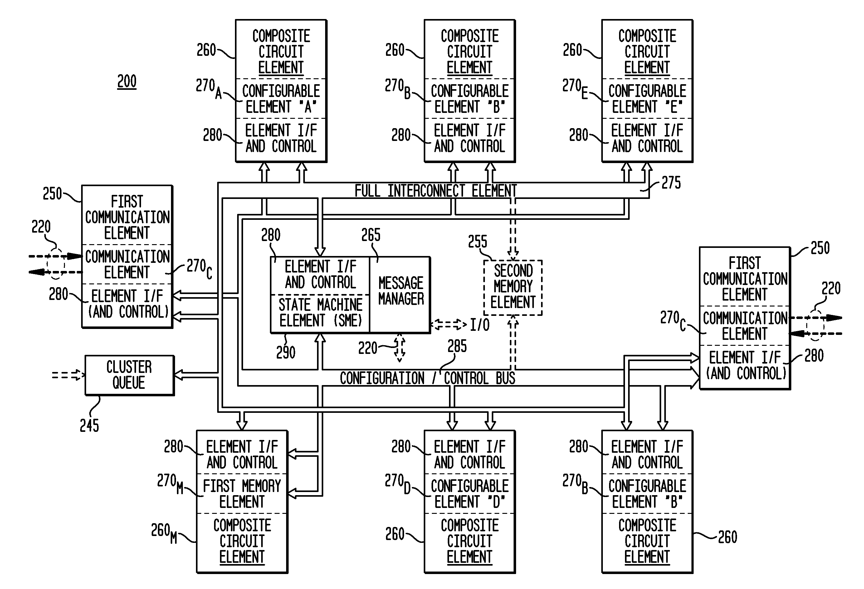
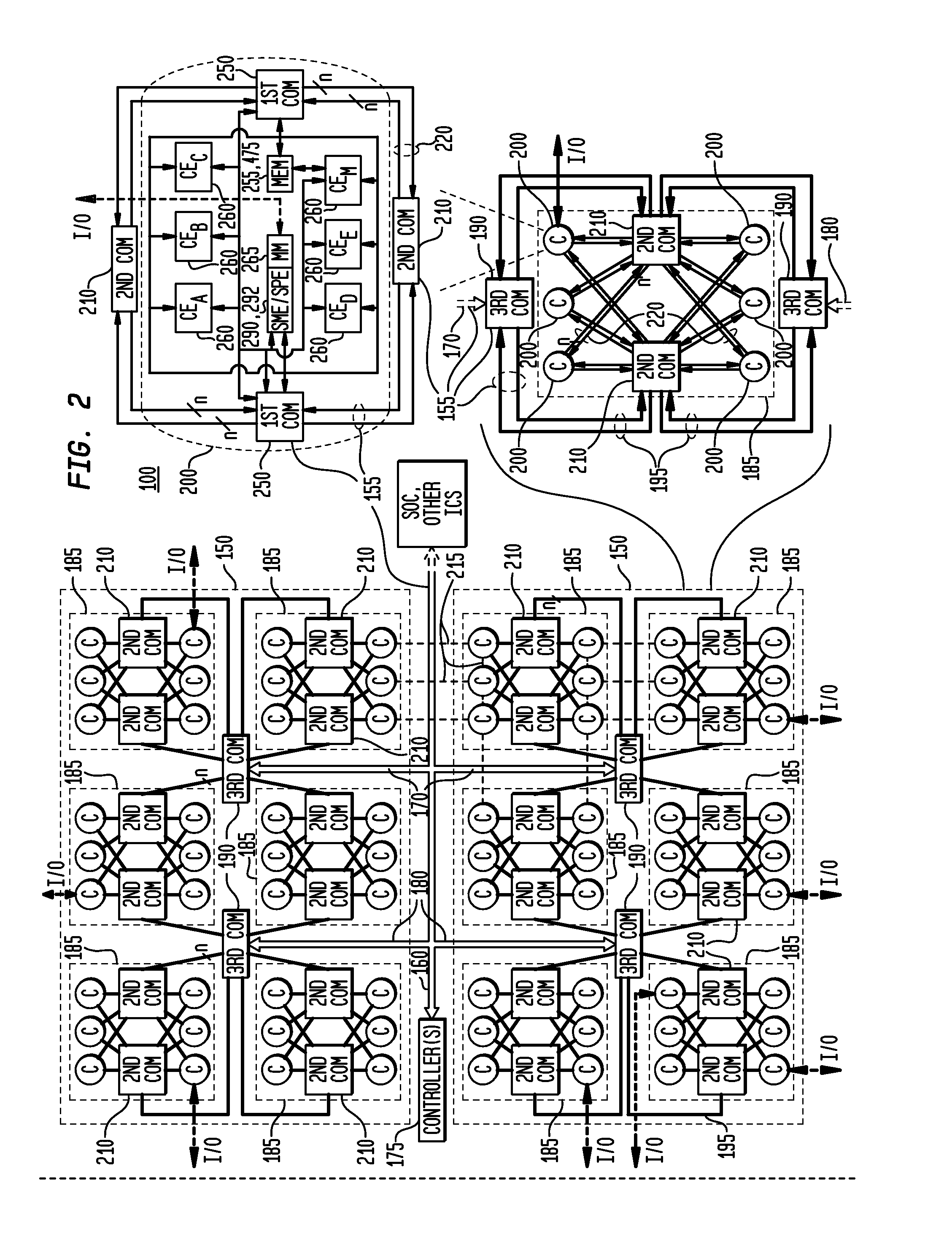
[0138]Each of the apparatuses 100, 140 typically is embodied as an integrated circuit, and may be a separate IC or part of a larger system-on-a-chip (“SOC”) or part of a network of ICs, such as coupled to other ICs on a circuit board, wiring network, network mesh, and so on. The two apparatus embodiments 100, 140 are illustrated as examples and typically differ in the location (and / or type) of the components and number of components within the various clusters 200, including the components utilized to provide input and output (“I / O”) to other, external or non-integrated ICs or other devices, such as external memory (e.g., DDR-2) or external communication channels or busses (e.g., PCI or PCI-express (PCI-e)). For apparatus 140, such external I / O has been concentrated within a selected matrix 150, while for apparatus 100, such external I / O has been distributed among a plurality of matrices 150. In FIG. 3, a message manager 265 has been utilized to implement a first communication eleme...

third embodiment

[0211]FIG. 7 is a block diagram illustrating a third exemplary cluster 200B embodiment in accordance with the teachings of the present invention, as another variation of a cluster 200. In this embodiment, the cluster 200B contains composite circuit elements 260 having communication functionality, such as to provide external communication functionality, e.g., for the communication functionality concentrated within a selected matrix 150 as illustrated in FIG. 3. Also in this embodiment, as an option, the message manager 265 is not utilized for such external communication, which instead is provided within dedicated communication composite circuit elements 260, which may be configurable or nonconfigurable. In this embodiment, each communication composite element 260 is utilized to provide a standard I / O interface for (external) communication to and from the apparatus 100, such as DDR-2 or PCI-e interfaces. In addition, the communication composite elements 260 may have additional input a...


PUM


Abstract

The exemplary embodiments provide a reconfigurable integrated circuit capable of on-chip configuration and reconfiguration, comprising: a plurality of configurable composite circuit elements; a configuration and control bus; a memory; and a sequential processor. Each composite circuit element comprises: a configurable circuit; and an element interface and control circuit, the element interface and control circuit comprising an element controller and at least one configuration and control register to store one or more configuration and control words. The configuration and control bus is coupled to the plurality of configurable composite circuit elements, and comprises a plurality of address and control lines and a plurality of data lines. The sequential processor can write configurations to the configuration and control registers of an addressed configurable composite circuit element to configure or reconfigure the configurable circuit.

Description

CROSS-REFERENCE TO RELATED APPLICATIONS[0001]This application is a conversion of and claims priority to: (1) Kelem, Steven Hennick et al., U.S. Provisional Patent Application Ser. No. 61 / 376,615, filed Aug. 24, 2010, entitled “Hierarchically Scalable Reconfigurable DDM Architecture With Unit-Delay Modules”; (2) Kelem, Steven Hennick et al., U.S. Provisional Patent Application Ser. No. 61 / 376,659, filed Aug. 24, 2010, entitled “Hierarchically Extensible Reconfigurable Zones in a Resilient Device Architecture”; (3) Kelem, Steven Hennick et al., U.S. Provisional Patent Application Ser. No. 61 / 376,662, filed Aug. 24, 2010, entitled “Multi-Context Memory Management Unit”; (4) Kelem, Steven Hennick et al., U.S. Provisional Patent Application Ser. No. 61 / 376,666, filed Aug. 24, 2010, entitled “On-Chip Configuration”; and (5) Kelem, Steven Hennick et al., U.S. Provisional Patent Application Ser. No. 61 / 376,672, filed Aug. 24, 2010, entitled “Data-Driven Integrated Circuit Architecture”; whi...

Claims


Application Information

Patent Timeline
Patent Type & Authority Applications(United States)
IPC IPC(8): G06F12/00
CPCG06F15/7867H03K19/007H03K19/17752G06F11/1428G06F12/0646G06F9/3897G06F11/1423H03K19/17756
Inventor BOX, BRIAN A.RUDOSKY, JOHN M.WASSON, STEPHEN L.KELEM, STEVEN HENNICK
Owner ELEMENT CXI
Why Eureka
Try Eureka