
Method and system for separating manganese-silicon casting iron scraps

A slag-iron separation, manganese-silicon technology, applied in mechanical cleaning, manufacturing tools, metal processing equipment, etc., can solve the problem of unsatisfactory slag-iron separation effect, and achieve the goal of improving the separation effect, reducing the amount of returned iron, and increasing the output. Effect

Active Publication Date: 2013-09-04
云南牧隆锰业有限公司
View PDF5 Cites 0 Cited by
  • Summary
  • Abstract
  • Description
  • Claims
  • Application Information

AI Technical Summary

Problems solved by technology

[0004] In addition, in the existing manganese-silicon pouring process, the method of natural cooling and pouring and filtering is adopted, and the separation effect of slag and iron is not ideal

Method used


Image

  • Method and system for separating manganese-silicon casting iron scraps
  • Method and system for separating manganese-silicon casting iron scraps
  • Method and system for separating manganese-silicon casting iron scraps

Examples


Embodiment Construction

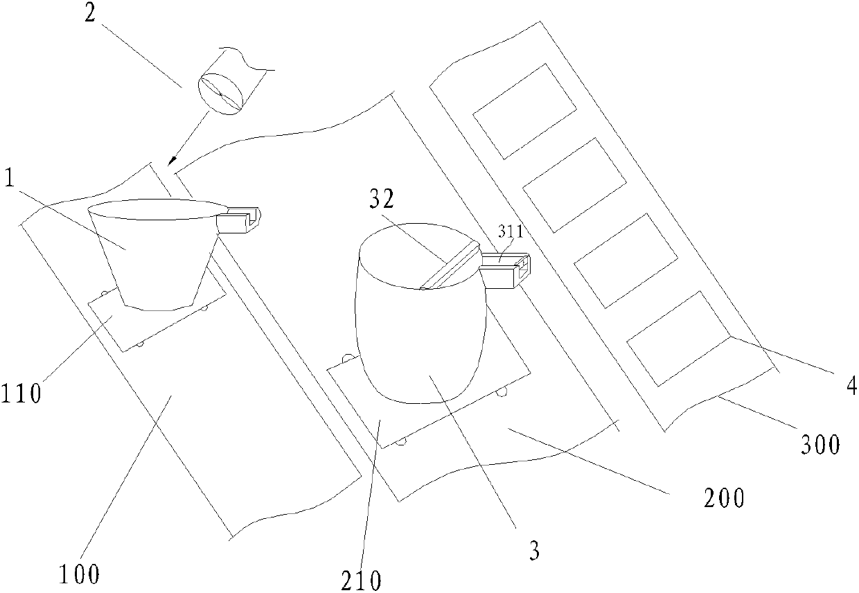
[0028] Embodiments of the present invention are described in detail below, examples of which are shown in the drawings, wherein the same or similar reference numerals designate the same or similar elements or elements having the same or similar functions throughout. The embodiments described below by referring to the figures are exemplary only for explaining the present invention and should not be construed as limiting the present invention.

[0029] In describing the present invention, it is to be understood that the terms "upper", "lower", "front", "rear", "left", "right", "top", "bottom", "inner", "outer" ” and other indicated orientations or positional relationships are based on the orientations or positional relationships shown in the accompanying drawings, which are only for the convenience of describing the present invention and simplifying the description, rather than indicating or implying that the referred device or element must have a specific orientation, with a spe...


PUM


Abstract

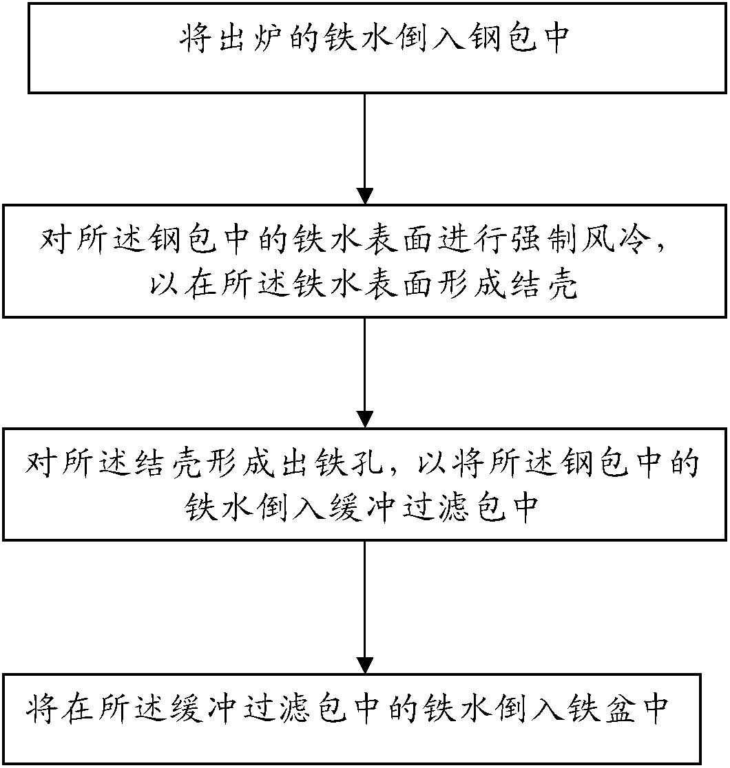
The invention discloses a method and system for separating manganese-silicon casting iron scraps. The method for separating manganese-silicon casting iron scraps comprises the following steps of: putting discharged molten iron into a steel ladle; performing forced air cooling on the surface of the molten iron in the steel ladle to form incrustation on the surface of the molten iron; forming an iron discharging hole on the incrustation to pour the molten iron in the steel ladle into a buffering filtering package; and pouring the molten iron in the buffering filtering package into an iron basin. Due to the adoption of the method for separating manganese-silicon casting iron scraps in the embodiment of the invention, the iron scrap separating effect is greatly improved, the yield is increased, and the sizing workload of operating personnel is lowered.

Description

technical field [0001] The invention relates to the field of manganese-ferroalloy manufacturing, in particular to an improved manganese-silicon casting slag-iron separation method and separation system. Background technique [0002] In the existing manganese silicon casting process, the specific casting process is as follows: [0003] Slag dumping→slag removal→coarse filtration. [0004] In addition, in the existing manganese-silicon pouring process, the method of natural cooling and pouring and filtering is adopted, and the separation effect of slag and iron is not ideal. Specifically, there are the following problems. [0005] First of all, during the furnace tapping process, due to the difference in specific gravity between the slag and the molten iron, the molten iron sinks to the bottom, while the slag floats on the surface of the molten iron. Under the premise of natural cooling, after the slag pouring and slag removal processes, a part of the slag will still remain...

Claims


Application Information

Patent Timeline
Patent Type & Authority Patents(China)
IPC IPC(8): B22D1/00B22D43/00
Inventor 杨忠姚汤顺祥杨选唐继洪蒋成瑞彭富波王永华韦祖林胡忠奎王运正魏霞
Owner 云南牧隆锰业有限公司
Learn More