

Coke oven stage residual coal cleaning machine
A technology for cleaning machines and stovetops, which is applied in coke ovens, furnaces to prevent/remove scale deposits, and petroleum industry. , the effect of low labor intensity
- Summary
- Abstract
- Description
- Claims
- Application Information
AI Technical Summary
Problems solved by technology
Method used
Image


Examples
Embodiment Construction
[0024] Typical embodiments embodying the features and advantages of the present invention will be described in detail in the following description. It should be understood that the present invention is capable of various changes in different embodiments without departing from the scope of the present invention, and that the description and drawings therein are illustrative in nature and not limiting. this invention.
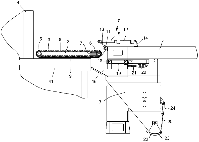
[0025] Such as figure 1 As shown, the present invention includes a moving device 1 , a bracket 2 and a scraper chain 3 . The mobile device 1 can select a coal loading car, a coke pushing car or an SCP all-in-one machine on the side of the coke oven 4 according to the situation. The main function of the mobile device 1 is to adjust measures to local conditions and move conveniently, so as to realize the cleaning of residual coal on the coking oven 4 hearth 41.
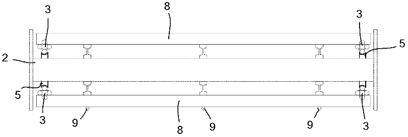
[0026] Such as figure 2 and image 3 As shown, the bracket 2 is a supporting structure, and the t...
PUM
 Abstract
Description
Claims
Application Information