Aspheric myopia eyeglass

An aspheric, myopic technology, applied in the field of optical spectacle lenses, can solve the problems of difficult processing, uncomfortable wearing, and difficult to process, and achieve the effects of being conducive to processing and manufacturing, high imaging quality, and outstanding stability

Active Publication Date: 2012-04-18
SUZHOU MASON OPTICAL CO LTD +1
View PDF7 Cites 11 Cited by
  • Summary
  • Abstract
  • Description
  • Claims
  • Application Information

AI Technical Summary

Problems solved by technology

[0002] The back surface and the front surface of the traditional spectacle lens are arc, the disadvantages of the arc spectacle lens are: poor imaging clarity, the same specification of the lens is thicker than the aspheric lens, heavy and uncomfortable to wear; therefore aspheric myopia The concept of spectacle lenses has been proposed. Aspherical myopia lenses have the advantages of thin lenses, light weight, comfortable wearing, and good imaging quality, but their processing is very difficult, and different design schemes will also cause uneven imaging quality, such as The application number is 200810021635.4, and the publication number is CN101650462A, the invention patent "double-sided aspheric resin lens". The data is compared with the parameters of the spherical spectacle lens designed according to the same power (-4D) as the spectacle lens of this embodiment, as shown in the table below:
[0006] First look at the image quality, from figure 1 and figure 2 It can be seen from the aberration curve diagram that the imaging quality of the double-sided aspheric resin lens provided by this technical solution is poor, and the specific performance is that the oblique astigmatism aberration is not as good as that of the spherical spectacle lens. For details, see meridian field curvature and sagittal field curvature. For numerical comparison, see the table below:

Method used


Image

  • Aspheric myopia eyeglass
  • Aspheric myopia eyeglass
  • Aspheric myopia eyeglass

Examples


Embodiment 1

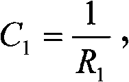
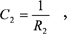
[0037] Such as image 3 As shown, an aspheric myopia lens includes a back surface 2 and a front surface 1, and the curved surfaces of the back surface 2 and the front surface 1 are even aspheric refracting surfaces, and the even aspheric refracting surfaces are determined by the following function:

[0038] Zm = Cm H 2 1 + 1 - ( 1 + K ) Cm 2 H 2 + Σ n = 2 8 A 2 n H ...

Embodiment 2

[0051] Such as image 3 As shown, an aspheric myopia lens includes an outer surface 1 and an inner surface 2, and the curved surfaces of the outer surface 1 and the inner surface 2 are even aspheric refracting surfaces, and the even aspheric refracting surfaces are determined by the following function:

[0052] Zm = CmH 2 1 + 1 - ( 1 + K ) Cm 2 H 2 + Σ n = 2 8 A 2 n H 2 ...

Embodiment 3

[0068] Such as image 3 As shown, an aspheric myopia lens includes an outer surface 1 and an inner surface 2, and the curved surfaces of the outer surface 1 and the inner surface 2 are even aspheric refracting surfaces, and the even aspheric refracting surfaces are determined by the following function:

[0069] Zm = CmH 2 1 + 1 - ( 1 + K ) Cm 2 H 2 + Σ n = 2 8 A 2 n H 2 ...


PUM


Abstract

The invention discloses an aspheric myopia eyeglass, comprising a back surface and a front surface. Curved surfaces of the back surface and the front surface are all aspheric even number aspheric refracting surfaces. The even number aspheric refracting surface is determined by a function as below; optimized variables are increased by times, so as to reach higher imaging quality and larger thinning amount. In addition, the even number aspheric refracting surface guarantees holosymmetry of the eyeglass and is beneficial for processing and manufacture; detection is same as a general spherical eyeglass, and measurement of degrees of eyeglass will not be influnced. The front surface and the back surface employ completely opposite aspheric design, so that various design errors and processing errors can compensate mutually. The eyeglass has excellent stability, and will not cause uncomfortableness to first time wearer due to various errors. Therefore, the aspheric myopia eyeglass has advantages of thin thickness, light weight, good imaging quality and facility for processing, etc.

Description

technical field [0001] The invention relates to an optical eyeglass lens, in particular to an aspheric myopia eyeglass lens. Background technique [0002] The back surface and the front surface of the traditional spectacle lens are arc, the disadvantages of the arc spectacle lens are: poor imaging clarity, the same specification of the lens is thicker than the aspheric lens, heavy and uncomfortable to wear; therefore aspheric myopia The concept of spectacle lenses has been proposed. Aspherical myopia lenses have the advantages of thin lenses, light weight, comfortable wearing, and good imaging quality, but their processing is very difficult, and different design schemes will also cause uneven imaging quality, such as The application number is 200810021635.4, and the publication number is CN101650462A, the invention patent "double-sided aspheric resin lens". The data is compared with the parameters of the spherical spectacle lens designed according to the same power (-4D) as...

Claims


Application Information

Patent Timeline
Patent Type & Authority Applications(China)
IPC IPC(8): G02C7/02
Inventor 徐光华余浩墨
Owner SUZHOU MASON OPTICAL CO LTD
Why Eureka
Try Eureka