Routing determination method and routing device

A technology for determining methods and routing, applied in digital transmission systems, electrical components, transmission systems, etc., and can solve problems such as routing failure to converge

Active Publication Date: 2012-04-18
BEIJING XINWANG RUIJIE NETWORK TECH CO LTD
View PDF3 Cites 12 Cited by
  • Summary
  • Abstract
  • Description
  • Claims
  • Application Information

AI Technical Summary

Problems solved by technology

[0010] The embodiment of the present invention provides a route determination method and routing device, which are used to solve the problem in the prior art when the broadcast link oscillates, and there are multiple routing devices at one end of the broadcast link, and no designated intermediate system is included. , the problem that the route cannot be converged after the route calculation

Method used


Image

  • Routing determination method and routing device
  • Routing determination method and routing device
  • Routing determination method and routing device

Examples


Embodiment 1

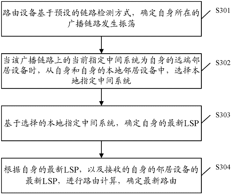
[0038] Figure 4 It is a flow chart of the route determination method provided in Embodiment 1 of the present invention. Each routing device applied to the broadcast link has established a neighbor relationship, has selected a designated intermediate system, and completed the route calculation scenario. Specifically, it includes the following Processing steps:

[0039] Step S401 , the routing device located on the broadcast link detects the broadcast link based on a preset link detection mode, and determines that the broadcast link oscillates.

[0040] Preferably, the preset link detection method can use the BFD method.

[0041] Generally, the broadcast link flaps between routing devices at both ends of the broadcast link, but does not flap between routing devices at the same end.

[0042] Step S402, the routing device judges whether the number of its own neighbor devices on the broadcast link is greater than 1, if yes, proceeds to step S403, otherwise, proceeds to step S409...

Embodiment 2

[0066] After completing the processing flow of the method for determining the route proposed in Embodiment 1 above, the routing devices at both ends of the broadcast link can establish a route through the backup line and perform data transmission through the backup line. However, since the broadcast link is in an oscillating state and is not completely interrupted, protocol messages between routing devices at both ends may also be transmitted on the broadcast link, such as HELLO messages and LSPs. The processing of the transmitted protocol message proposes the following processing flow in Embodiment 2 of the present invention, such as Figure 5 As shown, it specifically includes the following steps:

[0067] Step S501 , the routing device located on the broadcast link detects the broadcast link based on a preset link detection mode, and determines that the broadcast link oscillates.

[0068] Step S502, the routing device receives the protocol message sent by its neighbor devi...

Embodiment 3

[0078]After completing the processing flow of the route determination method proposed in the above-mentioned embodiment 1, when the broadcast link returns to normal from the oscillation state, the following processing flow of the route determination method is proposed in this embodiment 3, as follows: Figure 6 As shown, it specifically includes the following processing steps:

[0079] Step S601 , the routing device on the broadcast link detects the broadcast link based on a preset link detection mode, and determines that the broadcast link recovers from an oscillation state to a normal state.

[0080] Step S602, the routing device selects the latest designated intermediate system from among itself, its own remote neighbor devices and local neighbor devices. That is, the local neighbor device and the remote neighbor device jointly participate in the selection of the latest designated intermediate system.

[0081] When selecting the latest designated intermediate system, it ca...


PUM


Abstract

The invention discloses a routing determination method and a routing device. The method comprises the following steps: based on a preset link detection mode, the routing device determines that a broadcast link where the device is has oscillation; when a present assigned intermediate system at the broadcast link is a self distant end neighbor device, a local assigned intermediate system is selected from the device and a self local neighbor device; based on the selected local assigned intermediate system, a self latest LSP (link-state packet) is determined; according to the self latest LSP, and a received latest LSP of the neighbor device of the device, routing calculation is carried out, and a latest routing is determined. When the broadcast link has oscillation, one end of the broadcast link has a plurality of routing devices, and the assigned intermediate system is not included, by employing a scheme provided by an embodiment of the invention, the routing calculation is carried out, and routing convergence can be realized.

Description

technical field [0001] The present invention relates to the technical field of routing in the technical field of network communication, in particular to a routing determination method and routing equipment. Background technique [0002] With the development of network technology, more and more users use high-speed dedicated broadcast link (generally 10Mbps or more bandwidth) to replace low-speed DDN (DIGITAL DATA NETWORK, digital data network) dedicated line (general bandwidth around 2Mbps) for data transmission. For example, a typical example is that a bank uses an MSTP (Multi-Service Transport Platform, Multi-Service Transport Platform) line to replace the original low-speed DDN dedicated line for data transmission. The difference between MSTP lines and the well-known Ethernet broadband is that it is transparent to users or routing devices. For users or routing devices, it is equivalent to directly pulling a network cable from the operator side, that is, Ethernet access. ...

Claims


Application Information

Patent Timeline
Patent Type & Authority Applications(China)
IPC IPC(8): H04L12/56H04L12/721
Inventor 兰加兴
Owner BEIJING XINWANG RUIJIE NETWORK TECH CO LTD
Why Eureka
Try Eureka