
Packet network routing

a packet network and packet technology, applied in the field of packet network apparatus and methods, can solve the problems of packets to be dropped by the network, delay or loss of packets can be very expensive, and the extra processing required to generate interim routes is only carried ou

Active Publication Date: 2016-05-24
BRITISH TELECOMM PLC
View PDF12 Cites 3 Cited by
  • Summary
  • Abstract
  • Description
  • Claims
  • Application Information

AI Technical Summary

Benefits of technology

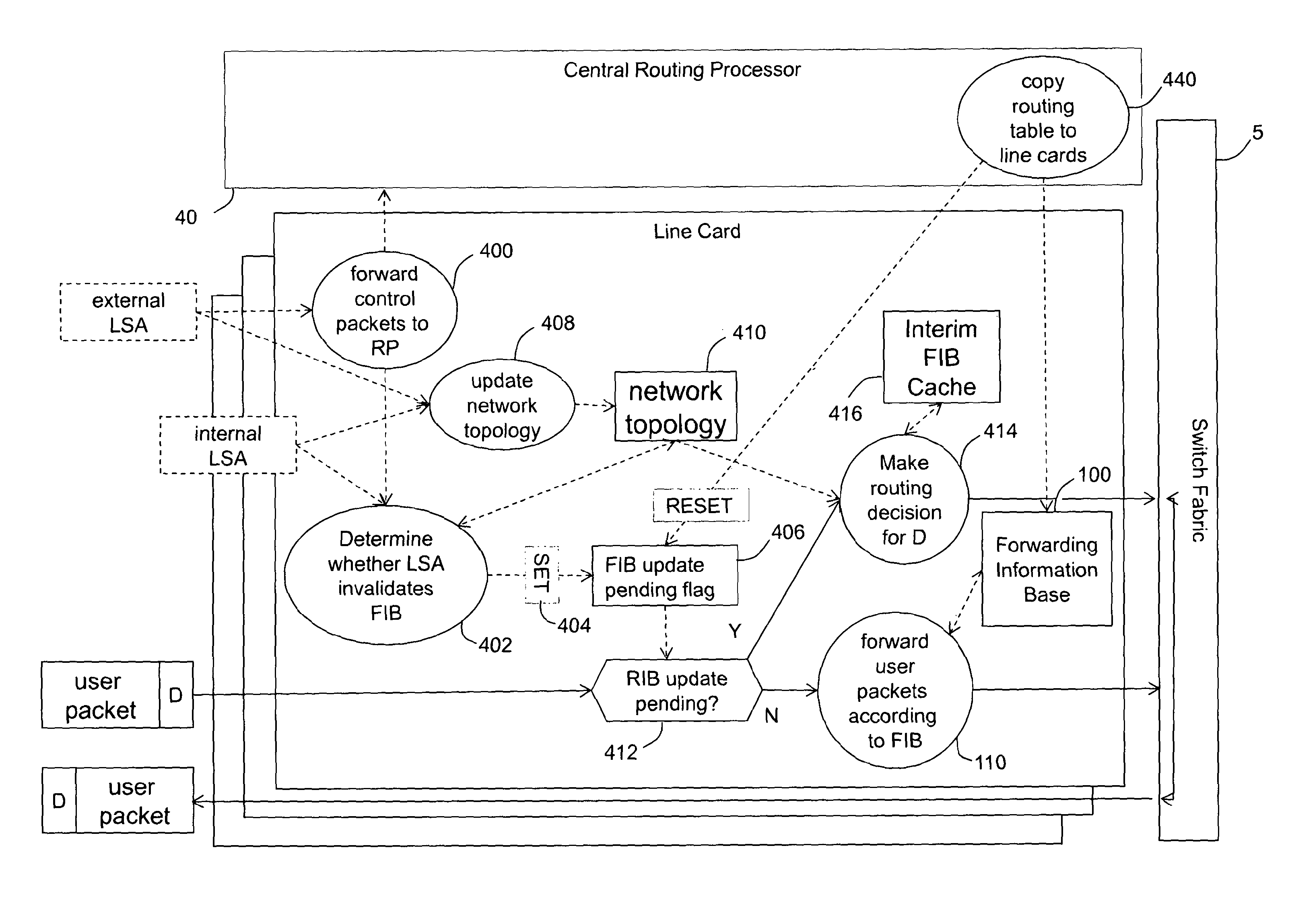
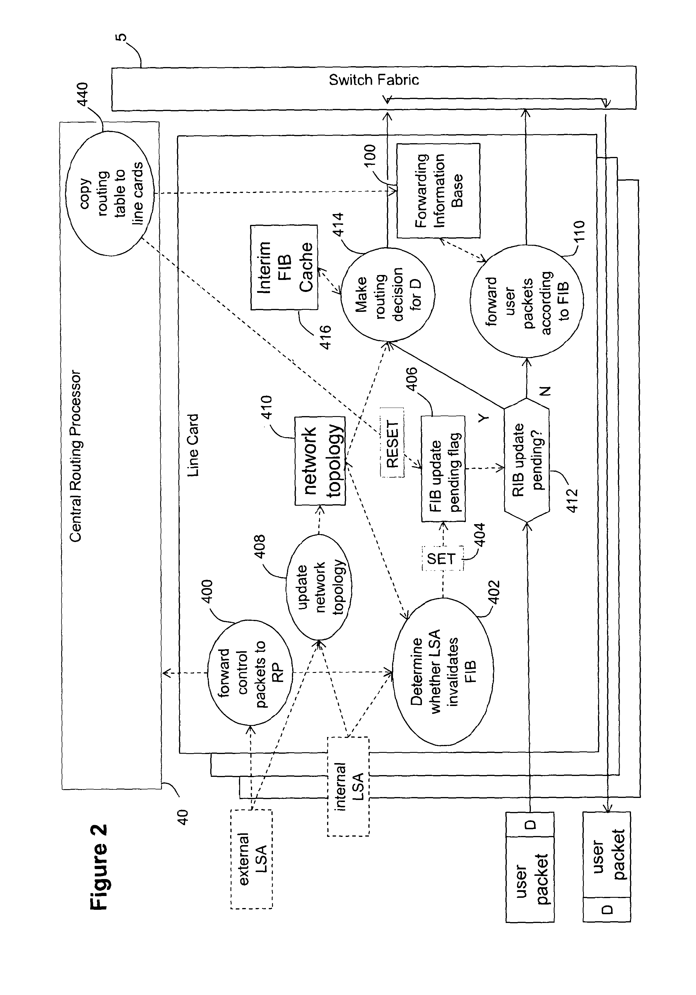
The patent is about a system for routing packets in a network. The invention aims to speed up the process of adapting to changes in network characteristics, which can cause delays or lost packets. The invention includes a line card that receives network state updates from other line cards and passes them to a shared routing processor. The line card calculates interim routes based on the network state updates and uses them to route incoming packets until a comprehensive set of routes is received. The technical effect of the invention is improved speed and efficiency in adapting to changes in network characteristics.

Problems solved by technology

This can lead to the mis-routing of hundreds of thousands of packets—in turn possibly leading to routing loops which at best cause delay and at worst cause the packet to be dropped by the network.
For some customers of network operators (e.g. financial traders running algorithmic trading systems) delay or loss of a packet can be very expensive.
This has the result that the extra processing required to generate interim routes is only carried out when required.

Method used


Image

  • Packet network routing
  • Packet network routing
  • Packet network routing

Examples


Embodiment Construction

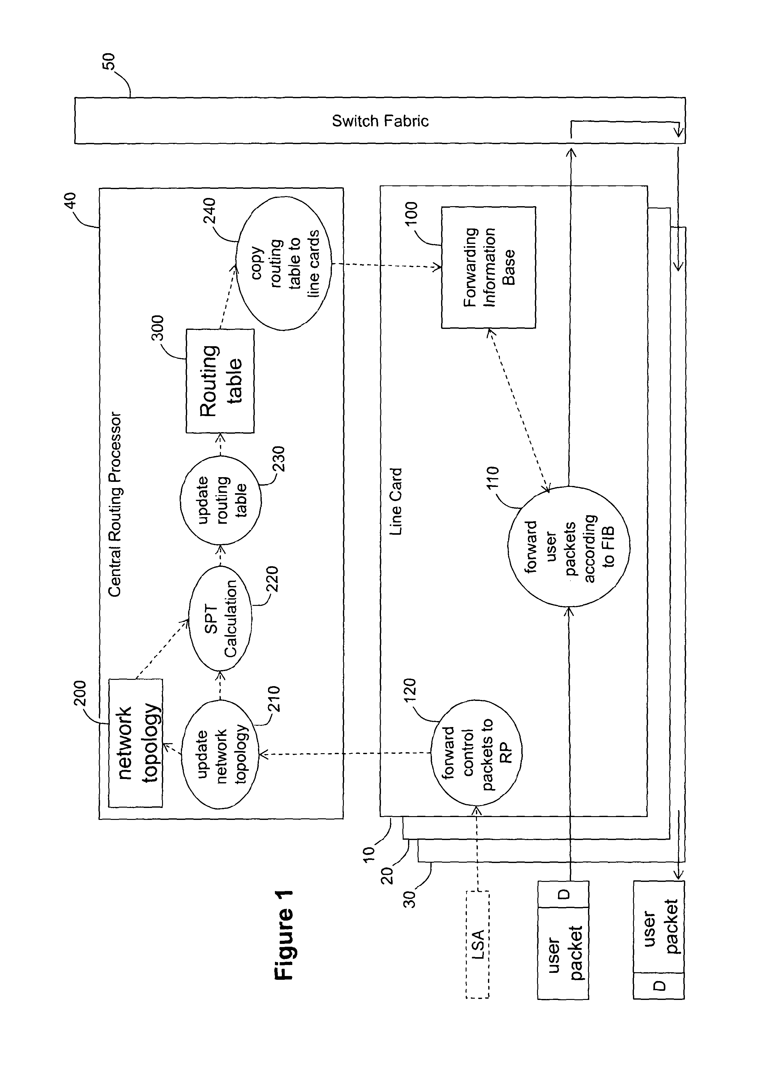
[0026]A conventional internetwork router (FIG. 1) comprises a card chassis (not shown) offering slots in which various types of electronic system boards (known as cards) are inserted. The various types of cards include line cards (10,20,30) which expose one or more physical ports onto which communication lines (e.g. optical fibres) can be connected. A second type of card is a route processor card 40 which performs centralised computations and management functions for the router. In particular, on the basis of network characteristic information packets received from the network via the line cards, the route processor card 40 calculates a network, topology and, from that, a shortest path tree to each node in the network. A third type of card is a switch fabric card 50 which routes data between line cards in accordance with routing information applied to the data by the line cards. The chassis provides physical connectors which connect to mating connectors on the back of the cards. The...


PUM


Abstract

A line card for use in a router or packet switch is disclosed. A problem with conventional routers or packet switches is that they can take over a second to fully react to a network state update from another router or packet switch. Such network state packets are used in dynamic routing protocols intended to route packets around a failed or overloaded router. In operating in according with dynamic routing protocols, conventional routers or packet switches react to such network state packets by updating the routing tables used by the line cards to send packets, or data extracted from packets, to the egress port (often on a different line card in the router or network switch) appropriate for the destination address found in the packet. Any packets which arrive between the network state packet's arrival and the completion of the ensuing routing table update on the line cards, can be misrouted—which can cause them to be delayed or dropped by the network. The described embodiments address this problem by operating the line card to react to a network state update packet by running a restricted routing algorithm to provide interim routes while a conventional comprehensive routing algorithm runs in parallel to provide a comprehensive set of routes. In this way, a faster, if less thorough, reaction to the arrival of a network state update packet is provided, which reduces the risk of packets being misrouted while the network converges. The technique has application to any packet networks, but is especially useful in Internet Protocol packet networks or Multi-Protocol Label Switching networks.

Description

[0001]This application is the U.S. national phase of International Application No. PCT / GB2013 / 000143 filed 28 Mar. 2013 which designated the U.S. and claims priority to EP 12250083.8 filed 30 Mar. 2012, the entire contents of each of which are hereby incorporated by reference.BACKGROUND AND SUMMARY[0002]The present invention relates to apparatus and methods for routing packets in a packet network.[0003]Whilst conventional routers in packet networks can forward millions of packets per second, their response to a signalling packet signalling a change in network characteristics can take more than a second. This can lead to the mis-routing of hundreds of thousands of packets—in turn possibly leading to routing loops which at best cause delay and at worst cause the packet to be dropped by the network. For some customers of network operators (e.g. financial traders running algorithmic trading systems) delay or loss of a packet can be very expensive. There is a need to speed up the process...

Claims


Application Information

Patent Timeline
Patent Type & Authority Patents(United States)
IPC IPC(8): H04L12/741H04L12/935H04L12/773H04L12/703H04L12/751H04L12/707H04L45/02H04L45/24H04L45/28H04L45/60H04L45/74H04L49/111
CPCH04L45/28H04L49/30H04L45/02H04L45/22H04L45/54H04L45/60H04L45/74
Inventor WILLIS, PETER
Owner BRITISH TELECOMM PLC
Learn More