
Mechanism to improve concurrency in execution of routing computation and routing information dissemination

a routing computation and concurrency technology, applied in the field of network communications, can solve the problem of limiting the time delay of rib update, and achieve the effect of optimizing the concurrency of flooding operations, reducing the number of computationally intensive routing-table computations, and efficient processing link-state packets

Active Publication Date: 2009-07-07
CISCO TECH INC
View PDF6 Cites 6 Cited by
  • Summary
  • Abstract
  • Description
  • Claims
  • Application Information

AI Technical Summary

Benefits of technology

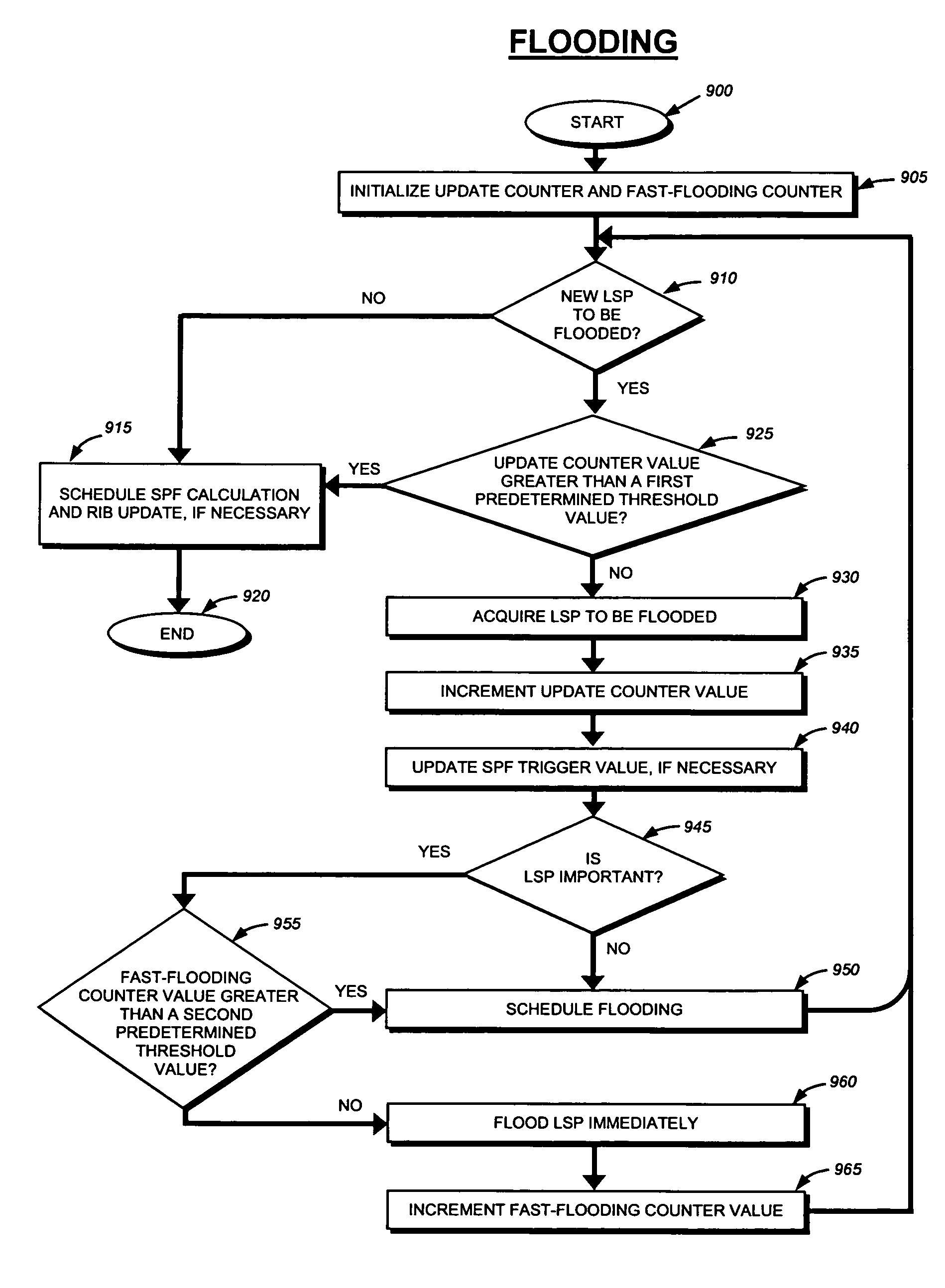
[0018]The present invention provides a technique for an intermediate network node, such as a router or switch, to efficiently process link-state packets using a single running context (i.e., process or thread). The technique optimizes the concurrency of flooding operations and routing-table computations that the node performs in accordance with link-state protocols. Unlike prior single-context implementations, the intermediate network node does not delay flooding until after the node's routing-table computations are completed. Instead, the node floods received link-state packets before performing shortest path first (SPF) calculations and routing information base (RIB) updates. Because a plurality of link-state packets may be flooded before routing-table computations are performed, the intermediate network node can perform a single set of SPF and RIB computations for the plurality of flooded packets, thereby reducing the number of computationally intensive routing-table computations conventionally performed.
[0019]In accordance with the present invention, the intermediate network node limits the number of link-state packets that can be flooded before the node performs SPF calculations. More specifically, if the number of link-state packets flooded during a “flooding cycle” exceeds a first predetermined threshold value, then the node stops its flooding operations and begins the SPF calculations. As used herein, a flooding cycle is a sequence of events performed by the intermediate network node as it floods one or more link-state packets. By imposing a limit on the number of flooded packets in this manner, the SPF calculations are not delayed an unreasonable amount of time as a result of excessive packet flooding.

Problems solved by technology

In addition, the intermediate network node also limits how long its RIB update may be delayed in favor of flooding operations.

Method used


Image

  • Mechanism to improve concurrency in execution of routing computation and routing information dissemination
  • Mechanism to improve concurrency in execution of routing computation and routing information dissemination
  • Mechanism to improve concurrency in execution of routing computation and routing information dissemination

Examples


Embodiment Construction

A. Intermediate Network Nodes

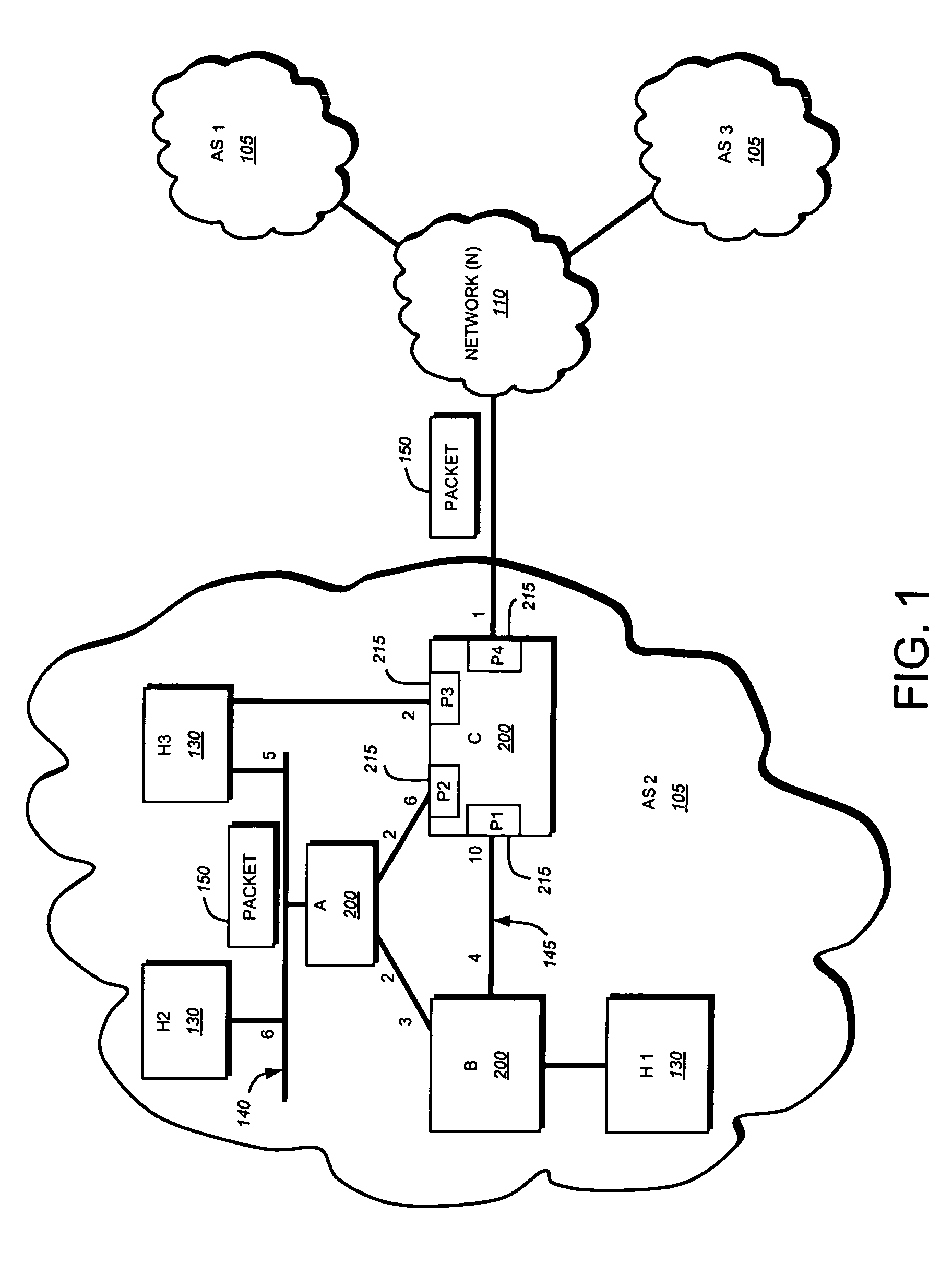
[0032]FIG. 1 is a schematic block diagram of an exemplary computer network 100 comprising a plurality of routing domains or autonomous systems 105 (AS1-AS3) interconnected by a network 110. Each autonomous system (AS) includes one or more network nodes, including client nodes 130 and intermediate network nodes 200. Typically, at least one intermediate node 200 is designated as a “gateway” node through which client communications can pass into and out of the AS 105. The gateway node may permit data packets 150 to be exchanged with other autonomous systems, i.e., through the network 110, using predefined network communication protocols such as the Transmission Control Protocol / Internet Protocol (TCP / IP), Asynchronous Transfer Mode (ATM) protocol, Frame Relay protocol, Internet Packet Exchange (IPX) protocol, etc.

[0033]Data packets 150 also may be communicated entirely within an autonomous system 105. For instance, the AS may include an intermediate network...


PUM


Abstract

A technique enables an intermediate network node to efficiently process link-state packets using a single running context (i.e., process or thread). The intermediate network node floods received link-state packets (LSP) before performing shortest path first (SPF) calculations and routing information base (RIB) updates. In addition, the node limits the number of LSPs that are permitted to be flooded before the node performs its SPF calculations. More specifically, if the number of link-state packets that are flooded during a flooding cycle exceeds a first predetermined threshold value, the node performs the SPF calculations before additional packets may be flooded. The intermediate network node also limits how long its RIB update may be delayed in favor of flooding operations. When the number of LSPs flooded after the SPF calculations exceeds a second predetermined threshold value or there are no more packets to be flooded, the node updates the contents of its RIB based on the SPF calculations.

Description

FIELD OF THE INVENTION[0001]This invention relates generally to network communications, and, more specifically, to an efficient technique for calculating and disseminating routing information by an intermediate network node, such as a router or switch.BACKGROUND INFORMATION[0002]A computer network is a geographically distributed collection of interconnected subnetworks for transporting data between network nodes, such as computers. A local area network (LAN) is an example of such a subnetwork. Since management of a large number of subnetworks can prove burdensome, the network may contain smaller groups of one or more subnetworks that may be managed as separate routing domains or autonomous systems (AS). The network topology is defined by an arrangement of client nodes that communicate with one another, typically through one or more intermediate network nodes, such as a router or switch. As used herein, a client node is an endstation node that is configured to originate or terminate ...

Claims


Application Information

Patent Timeline
Patent Type & Authority Patents(United States)
IPC IPC(8): H04L12/28
CPCH04L45/02H04L45/12H04L45/56H04L49/9078H04L47/6235H04L49/90H04L47/24H04L45/03
Inventor PREVIDI, STEFANO B.FILSFILS, CLARENCEWARD, DAVID D.
Owner CISCO TECH INC
Learn More