Variable translucency no-sight routing for AD-HOC networks

a no-sight routing and ad-hoc technology, applied in data switching networks, frequency-division multiplexes, instruments, etc., can solve the problems of ad-hoc network topology that is subject to rapid changes, network management and routing techniques that have not been improved in recent years, and conventional routing approaches (commonly known as “link-state” routing) suffer from a number of limitations

Inactive Publication Date: 2012-03-27
RAYTHEON BBN TECH CORP +1
View PDF57 Cites 4 Cited by
  • Summary
  • Abstract
  • Description
  • Claims
  • Application Information

AI Technical Summary

Problems solved by technology

Due to the mobility of the devices involved, the topology of ad-hoc networks is typically subject to rapid changes, such as when devices are added, removed or moved from one location to another within the network.
Ad-hoc networks face a number of challenges.
Although physical layer connectivity is, of course, a prerequisite for network connectivity, recent improvements in physical connectivity have not been matched by improvements in network management and routing techniques.
Although relatively simple in its implementation, this conventional routing approach (commonly known as “link-state” routing) suffers from a number of limitations, particularly when adapted for use in wireless ad-hoc networks.
When the amount of link-state traffic exceeds the physical capabilities of the hardware of the network, the network may become unreliable or fail.
Thus, unacceptable increases in the amount of link-state data and traffic serve to limit the network's scalability potential by inhibiting the number of nodes that may feasibly connect to the network.
In addition, because switching nodes in a link-state routing scheme are required to transmit LSUs upon every perceived change in network topology, an inordinate number of LSUs may be propagated within the network due to the relatively high frequency with which topology changes occur in ad-hoc networks.
This results in large amounts of routing traffic overhead being transmitted within the network, which may further limit the workable size of the ad-hoc network and lead to degradation of network performance and reliability.
Because global LSUs are only transmitted within this hazy-sighted routing scheme on a periodic basis, during certain periods of time various nodes within a net...

Method used


Image

  • Variable translucency no-sight routing for AD-HOC networks
  • Variable translucency no-sight routing for AD-HOC networks
  • Variable translucency no-sight routing for AD-HOC networks

Examples


Embodiment Construction

I. System Overview

[0023]a. No Sight Routing

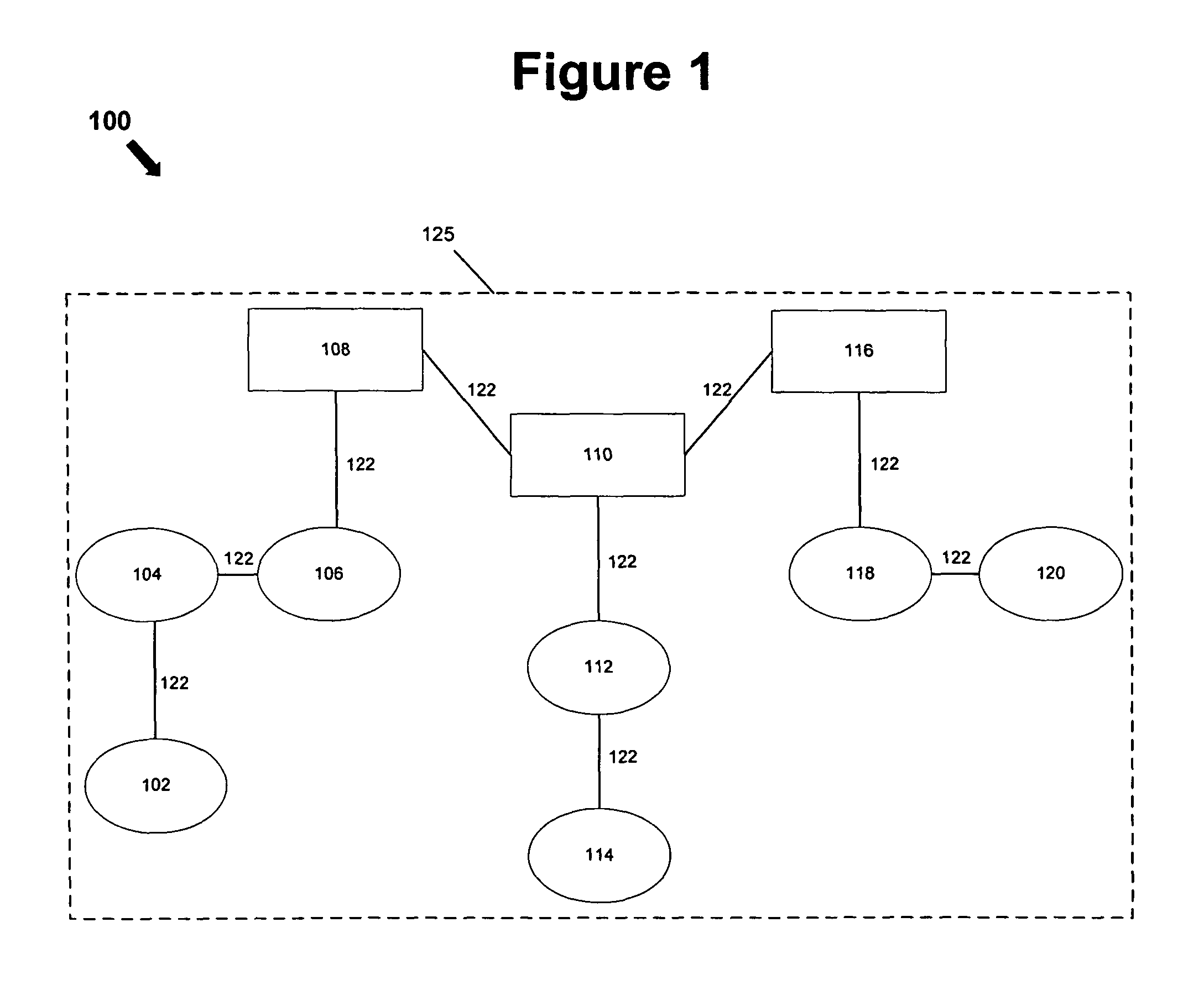
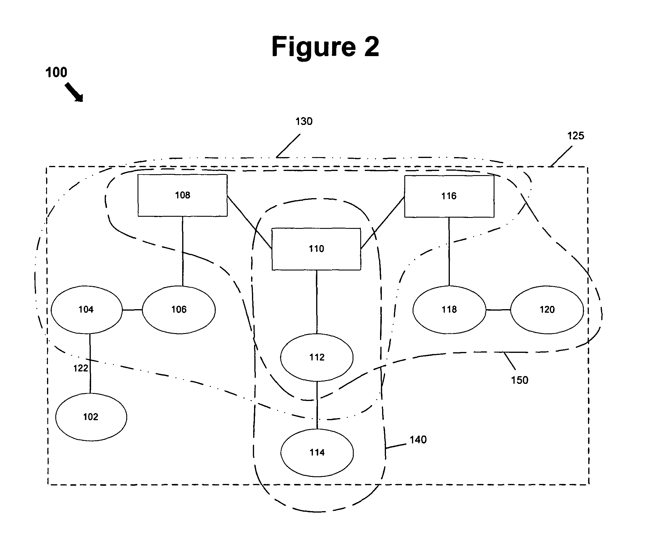
[0024]FIG. 1 is a block diagram illustrating an exemplary physical infrastructure of a system 100 for implementing a no-sight routing protocol. FIG. 2 illustrates an exemplary physical topology of a sub-network 125 implementing an exemplary no-sight routing protocol with predetermined propagation limits.

[0025]Exemplary system 100 generally comprises, among other things, nodes 102, 104, 106, 108, 110, 112, 114, 116, 118 and 120. Nodes 102-120 are connected to one another via connections 122, which may include any number of connections recognized in the art, including, for example, wires, wireless communication links, fiber optic cables, etc. Nodes 102-120 connected together via connections 122 collectively form sub-network 125.

[0026]In general, nodes 102-120 represent connection terminals within exemplary sub-network 125. In some embodiments, a protocol operating on a network above that of sub-network 125 distinguishes between nodes 102-120 ...


PUM


Abstract

A system comprising a plurality of nodes forming a network and a link-state packet capable of being transmitted by a source node in the network to a destination node in the network over a communication link; wherein the source node subtracts a transmission cost associated with the communication link from a time-to-live value associated with the link-state packet prior to transmitting the link-state packet to the destination node. Each node in the network may be configured to use a routing protocol, such as a no-sight routing protocol, to assign the transmission cost to the communication link.

Description

RELATED APPLICATIONS[0001]The present application claims priority from U.S. Provisional Patent Application No. 60 / 555,970, entitled “NO-SIGHT ROUTING FOR AD-HOC NETWORKS”, filed on Mar. 25, 2004. In addition, the present application is related to U.S. Patent Application No. 60 / 555,980, entitled “NO-SIGHT ROUTING FOR AD-HOC NETWORKS”, filed on the same day as the instant application. The contents of both of these applications are hereby incorporated by reference in their entirety.[0002]Certain subject matter disclosed and claimed herein was developed under a contract with the United States government (No. N00014-03-C-0230). The U.S. government has certain rights in this application.BACKGROUND INFORMATION[0003]In recent years, the use of wireless communication networks as a system for facilitating communication between various types of mobile devices, such as portable computers, personal digital assistants (“PDAs”), cellular telephones and the like, has gained widespread acceptance. I...

Claims


Application Information

Patent Timeline
IPC IPC(8): G01R31/08G06F11/00G08C15/00H04J1/16H04J3/14H04L1/00H04L12/26H04W40/00H04L45/24
CPCH04L45/00H04L47/2441H04L41/0896H04W40/12H04L45/123H04L45/24H04L47/286
Inventor TROXEL, GREGORY DONALDRAMANATHAN, SUBRAMANIAN
Owner RAYTHEON BBN TECH CORP
Why Eureka
Try Eureka