Curved glass or glass ceramic moulded part and method for producing same

A glass-ceramic and glass-forming technology, which is applied in the field of manufacturing curved glass moldings or glass-ceramic moldings, and can solve problems such as interruption of glass layers

Active Publication Date: 2012-04-25
SCHOTT AG
View PDF5 Cites 1 Cited by
  • Summary
  • Abstract
  • Description
  • Claims
  • Application Information

AI Technical Summary

Problems solved by technology

If the ceramization is performed before cutting to final size (this simplifies the ceramization step since the tube is ceramized standing without costly supporting components), this has the following Disadvantage, namely: when ceramizing the entire surface, the resulting glass layer is interrupted at all processing points

Method used


Image

  • Curved glass or glass ceramic moulded part and method for producing same
  • Curved glass or glass ceramic moulded part and method for producing same
  • Curved glass or glass ceramic moulded part and method for producing same

Examples


Embodiment Construction

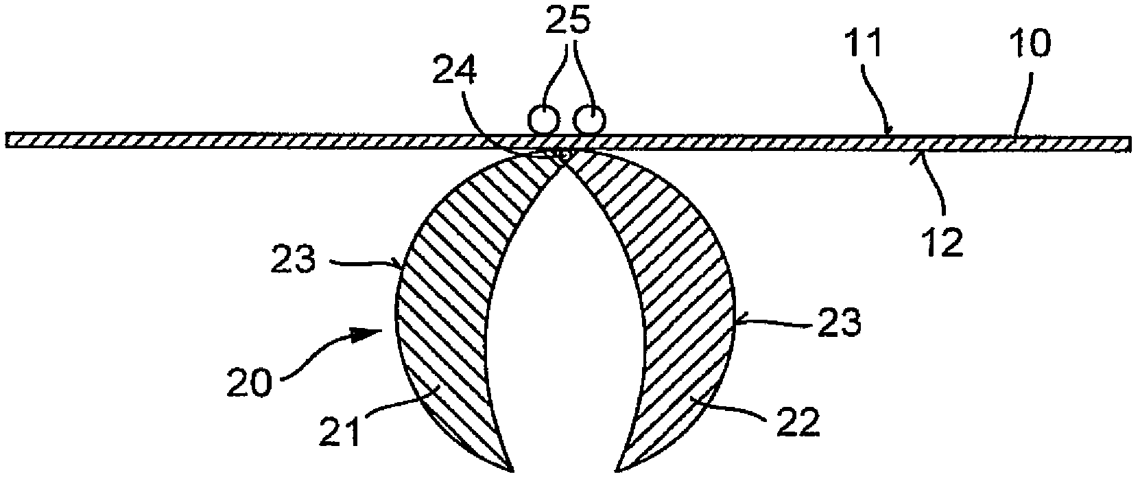
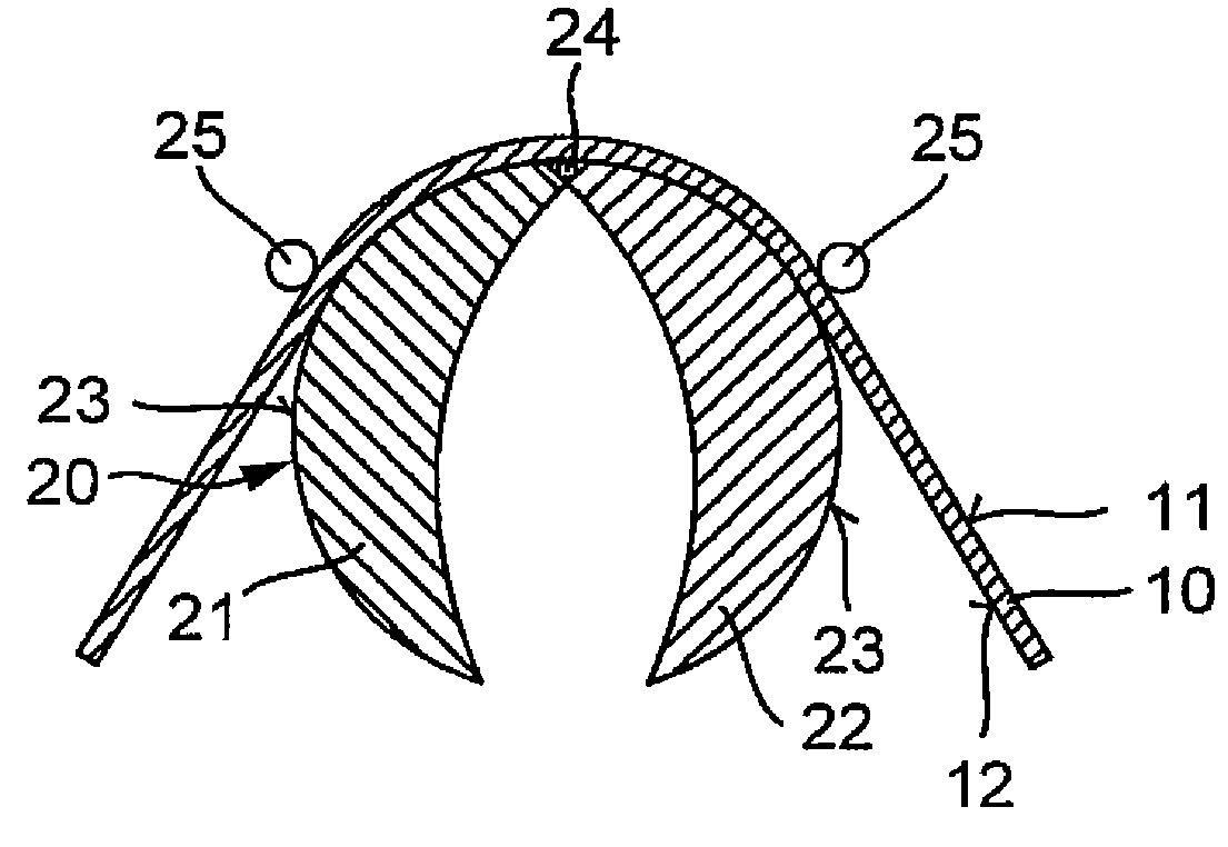
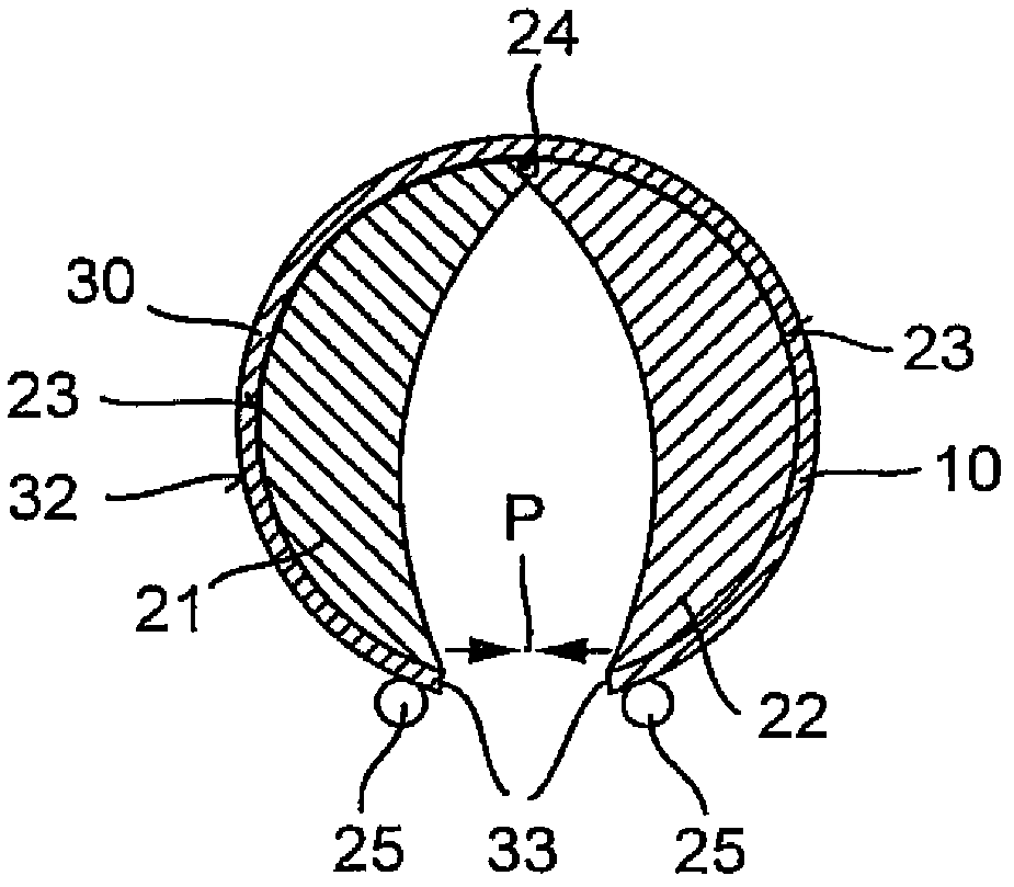
[0027] figure 1 A mold 20 is shown, which has two molded parts 21 and 22 that can move toward each other. Here, the two supporting bodies 21 and 22 are coupled around a movable connecting piece 24. Preferably, the movable connecting piece is formed by a hinge having a pivot axis. The two supporting bodies 21 and 22 respectively have an arc-shaped supporting surface 23, wherein the two supporting surfaces 23 realize a common partial cylindrical plane. In the area of ​​the movable connecting element 24, a rectangular or square green glass cutting section 10 is arranged. Green glass cutting sections 10 of other contour shapes are also conceivable. The blank glass cut section 10 is placed above the support bodies 21 and 22 with its bottom side 12. Two pressing devices 25 act on the upper side 11 of the blank glass cutting section 10. The two pressing devices 25 hold the cut section of green glass on the supporting surface 23. In the next method step, the green glass cutting s...


PUM

PropertyMeasurementUnit
diameteraaaaaaaaaa

Abstract

The process comprises introducing a green glass blank (10) in a temperature state in which its viscosity enables a deformation, and molding the green glass blank on a curved support surface (23) of a molding tool (20). The green glass blank is: molded on the support surface during the remolding process using a movable blank-holder (25); deformed in the region between the blank holder and the support surface and by two oppositely traversed blank holder; ceramized after its deformation; and provided with a decorative coating and / or a functional coating before its transformation. The process comprises introducing a green glass blank (10) in a temperature state in which its viscosity enables a deformation, and molding the green glass blank on a curved support surface (23) of a molding tool (20). The green glass blank is: molded on the support surface during the remolding process using a movable blank-holder (25); deformed in the region between the blank holder and the support surface and by two oppositely traversed blank holder; ceramized after its deformation; and provided with a decorative coating and / or a functional coating before its transformation. The blank-holder is: moved along the curved support surface during the remolding process; unrolled by rollers on the green glass blank; moved into a final forming position in which it rests on the deformed green glass blank; and kept in the cooling phase of the green glass blank formed glass or glass ceramic mold part in the final forming position. An INDEPENDENT CLAIM is included for a glass- or glass ceramic-mold part.

Description

Technical field [0001] The invention relates to a glass molded part or a glass ceramic molded part with an arc-shaped component area. [0002] The present invention also relates to a method for manufacturing curved glass molded parts or glass ceramic molded parts, wherein the green glass cut section / primary glass cut section (Grünglaszuschnitt) is sent to the following temperature state, in the In the temperature state, the viscosity of the cut section of the green glass makes the deformation possible, and wherein the cut section of the green glass is formed on the curved supporting surface of the mold. Background technique [0003] A method for producing such glass ceramic molded parts is known from DE 10102576 A1. Here, a mold is used which has a mold-shaped receiving area. The blank glass cutting section is positioned through the containment area, and is transformed into a plastic state under the action of temperature in the following way, that is, the blank glass sinks into t...

Claims


Application Information

Patent Timeline
Patent Type & Authority Applications(China)
IPC IPC(8): C03B23/03
CPCC03B23/0256C03B32/02Y10T428/24628
Inventor 奥利弗·穆勒克弗兰克·克拉姆菲尔茨
Owner SCHOTT AG
Why Eureka
Try Eureka