Frictional torque compensation method and device as well as idle speed control method and system

A technology of friction torque and compensation method, which is applied in the direction of engine control, machine/engine, mechanical equipment, etc. It can solve problems such as unstable idle speed and engine friction torque difference, and achieve the effect of stable idle speed control

Inactive Publication Date: 2012-04-25
CHERY AUTOMOBILE CO LTD
View PDF6 Cites 19 Cited by
  • Summary
  • Abstract
  • Description
  • Claims
  • Application Information

AI Technical Summary

Problems solved by technology

Although the production process and performance requirements of the same batch of engines are the same, due to the individual differences between the engines that may occur in the production process and the different running-in degrees of each engine in subsequent use, resulting in the actual use process. The friction torque of the engine of each vehicle will be more or less different
Then in actual use, the current friction torque of the engine obtained by the electronic control part by querying the pre-stored parameter map may have a large difference from the actual friction torque. If the difference is large, it will cause problems such as unstable idle speed.

Method used


Image

  • Frictional torque compensation method and device as well as idle speed control method and system
  • Frictional torque compensation method and device as well as idle speed control method and system
  • Frictional torque compensation method and device as well as idle speed control method and system

Examples


Embodiment 1

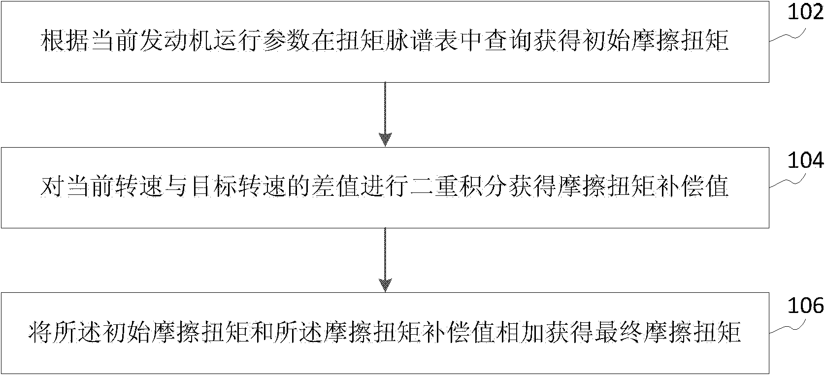
[0053] Please refer to figure 1, which shows a flow chart of the friction torque compensation method provided by Embodiment 1 of the present invention. The friction torque compensation method is suitable for an engine control system with a pre-stored torque map table, and the friction torque compensation method includes:

[0054] Step 102, querying the torque map table according to the current engine operating parameters to obtain the initial friction torque;

[0055] First of all, it should be explained that during the calibration process of vehicle production, technicians will store a more comprehensive representation of the engine in the ROM memory of the same batch of engines or the electronic control part of the vehicle based on the experiment or test results of the calibration engine. Performance parameter values, parameter curves or parameter map tables. In one embodiment, the parameter map is the universal characteristic curve of the engine, which can include various...

Embodiment 2

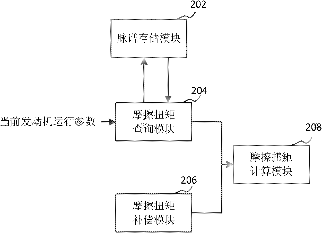
[0066] Please refer to figure 2 , which shows a structural block diagram of the friction torque compensation device provided by Embodiment 2 of the present invention. The friction torque compensation device includes a map storage module 202 , a friction torque query module 204 , a friction torque compensation module 206 and a friction torque calculation module 208 .

[0067] The map storage module 202 stores the torque map table of the engine. The torque map table is a parameter map table pre-stored in the ROM memory of the electronic control part during the calibration process of the production or maintenance vehicle. Usually the torque map table is part of the engine universal curve table. The torque map table can be queried by some engine parameters to obtain the corresponding torque value. For example, when the engine is in an idling condition, the friction torque of the engine can be obtained by querying the current engine speed and intake air volume. The friction to...

Embodiment 3

[0073] Please refer to Figure 4 , which shows a method flowchart of the idle speed control method provided by the embodiment of the present invention. The idle speed control method is applicable to an engine control system with a pre-stored torque map table, and the idle speed control method includes:

[0074] Step 402, querying the torque map table according to the current engine operating parameters to obtain the initial friction torque;

[0075] In an engine control system with a pre-stored torque map table, when the engine is in the idle state, the current engine operating parameters can be collected through sensors such as the speed sensor, the throttle rotation angle sensor, etc., and then passed such as the current speed, the current The current engine operating parameters such as intake air volume are used to query the torque map table to obtain the initial friction torque.

[0076] Step 404, performing double integration on the difference between the current rotati...


PUM


Abstract

The invention discloses a frictional torque compensation method and device as well as an idle speed control method and system and belongs to the field of automobile electronic control. The frictional torque compensation method comprises the following steps: inquiring an initial frictional torque from a prestored torque pulse spectrum table according to the current engine operating parameter; carrying out double integration on the D-value of the current revolving speed and a target revolving speed to obtain a frictional torque compensation value; and adding the initial frictional torque and the frictional torque compensation value together to obtain a final frictional torque. The frictional torque compensation system realizes the frictional torque compensation method, and the idle speed control method and an idle speed control system utilize the final frictional torque acquired by the compensation to carry out idle speed control; the D-value of the current revolving speed and the target revolving speed is subjected to double integration so as to obtain the frictional torque compensation value, thereby effectively reducing or eliminating the difference of the frictional torque obtained through searching the table and the actual frictional torque of an engine; and the final frictional torque after compensation is utilized to realize more stable idle speed control.

Description

technical field [0001] The invention relates to the field of automotive electronic control, in particular to a friction torque compensation method, device, idle speed control method and system. Background technique [0002] The idling condition of the engine refers to the stable operation of the engine at the lowest speed when there is basically no power output to the outside world. When idling, if the speed is stable, the output torque of the engine is just in balance with the resistance torque. In the case where the power of the engine is not used to drive the driven device such as a car at all, the task of idling is only to keep the engine from stalling, rather than acting externally. The fuel consumed at idle speed is completely used to overcome friction and other resistances. [0003] The stability control of idle speed is an important task in the research of engine control, and the idle speed control system is also an important part of the engine control system. In ...

Claims


Application Information

Patent Timeline
Patent Type & Authority Applications(China)
IPC IPC(8): F02D29/02
Inventor 李康
Owner CHERY AUTOMOBILE CO LTD
Why Eureka
Try Eureka