
Method and device for displaying three-dimensional image

A technology of stereoscopic images and images, applied in the field of image processing, can solve the problems of stereoscopic images occupying bandwidth and being unable to be displayed on flat-panel displays, etc., and achieve good stereoscopic effects, convenient viewing, and no flickering effects

Active Publication Date: 2012-04-25
SHENZHEN SKYWORTH RGB ELECTRONICS CO LTD
View PDF4 Cites 7 Cited by
  • Summary
  • Abstract
  • Description
  • Claims
  • Application Information

AI Technical Summary

Problems solved by technology

[0003] The purpose of the embodiments of the present invention is to provide a method for displaying stereoscopic images, aiming to solve the problem that existing 3D display technologies cannot use flat-panel displays to display better stereoscopic images and occupy bandwidth

Method used


Image

  • Method and device for displaying three-dimensional image
  • Method and device for displaying three-dimensional image
  • Method and device for displaying three-dimensional image

Examples


Embodiment 1

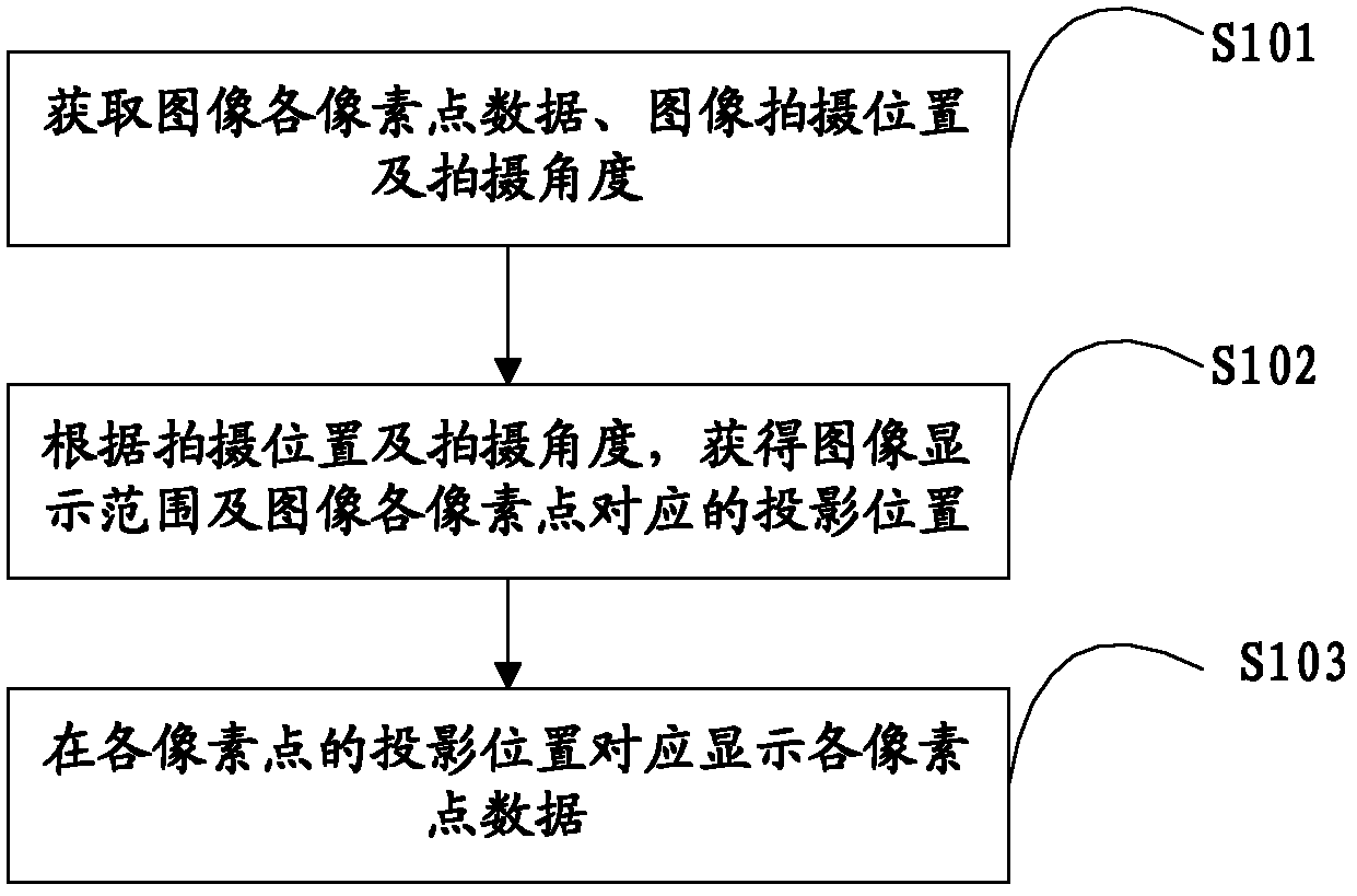
[0031] Such as figure 1 What is shown is a flow chart of the method for displaying a stereoscopic image provided by the present invention, and for the convenience of description, only the parts related to the embodiment of the present invention are shown.

[0032] In step S101, data of each pixel point of the image, image shooting position and shooting angle are acquired.

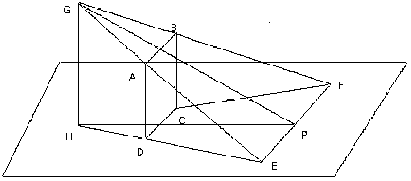
[0033] In the embodiment of the present invention, before displaying an image, the image information to be displayed must first be obtained, that is, the data of each pixel of the image, and the data of each pixel of the image is the data of each pixel of the image when shooting, that is, figure 2 The original image ABCD in .

[0034] Secondly, to obtain the shooting position and shooting angle of the image, the shooting position and shooting angle can be transmitted to the display system at the beginning of the data transmission of each pixel of the image. Specifically, in order to enable the image to d...

Embodiment 2

[0053] Figure 5 The schematic structural diagram of the device for displaying stereoscopic images provided by the embodiment of the present invention, for the convenience of description, only shows the parts related to the embodiment of the present invention. in:

[0054] The data acquisition unit 51 is configured to acquire the data of each pixel point of the image, the image shooting position and the shooting angle.

[0055] In the embodiment of the present invention, oblique top view shooting is adopted, the shooting angle is greater than 0° and less than 90°, and the data of each pixel of the image is the data of each pixel of the image when shooting.

[0056] Preferably, in order to ensure the 3D display effect, the shooting angle ranges from 30° to 60°. Among them, when the shooting angle is 45°, the 3D imaging effect of the image is the best.

[0057] The projection calculation unit 52 is configured to obtain the image display range and the projection position corre...


PUM


Abstract

The invention is applied to the field of image processing, providing a method and device for displaying a three-dimensional image. The method comprises the following steps of: acquiring each pixel point data, the shooting position and the shooting angle of an image; acquiring the display range of the image and the projection position corresponding to each pixel point of the image; and correspondingly displaying each pixel point data at the projection position of each pixel point. According to the method and device disclosed by the invention, the image is subjected to extension processing by adopting a mode of inclined overlook shooting and non-verticality of a display surface to the watching view during display, so that a looker can watch the three-dimensional image within a specified display range by using a two-dimensional display. The problems that the three-dimensional image cannot be displayed by using a two-dimensional display and 3D glasses are required to be worn and the requirement on a transmission line is high in a traditional 3D display technology are solved.

Description

technical field [0001] The invention belongs to the field of image processing, in particular to a method and device for displaying stereoscopic images. Background technique [0002] With the advancement of technology, 3D display has become the mainstream image display technology, and 3D movies and 3D pictures have become popular in the market. At present, the method of transmitting different images to the left and right eyes is generally adopted, and after being processed by the brain, people can see a 3D stereoscopic effect. However, no matter the left and right eye images are processed by the polarization method, or the 3D images are displayed stereoscopically by the shutter method, the viewer must wear special 3D glasses to watch the 3D stereoscopic effect. Wearing 3D glasses will cause inconvenience to the viewer, and will cause problems of crosstalk and visual fatigue, making it difficult to obtain a perfect viewing experience. In addition, the grating method can also...

Claims


Application Information

Patent Timeline
IPC IPC(8): H04N13/00
Inventor 王俊许锟袁彩凤
Owner SHENZHEN SKYWORTH RGB ELECTRONICS CO LTD
Learn More