Mold and molding technology of special-shaped inlet air pipe,

A molding process and air intake pipe technology, which is applied in the field of mold and forming process of special-shaped air intake pipes, can solve the problems of excess blanks and flashes, large differences in wall thickness, and failure to blow molding, so as to solve the problem of uneven wall thickness, The effect of uniform wall thickness and high forming rate

Active Publication Date: 2012-05-02
NINGBO JOYSONQUIN AUTOMOTIVE SYST HLDG CO LTD
View PDF13 Cites 6 Cited by
  • Summary
  • Abstract
  • Description
  • Claims
  • Application Information

AI Technical Summary

Problems solved by technology

The mold for this kind of special-shaped intake pipe is developed according to the traditional thinking, and the upper and lower cavities are divided as evenly as possible. The process adopts traditional 3D blow molding, which will lead to a very large difference in the overall wall thickness of the formed pipe, and may also be caused by the wall thickness. The difference is large, and blowing does not shape
If 2D blow molding is used, excess blanks and flashes will appear at the parting line, and the performance and appearance requirements of the intake pipe cannot be met.
[0006] To sum up, at present, no matter whether the special-shaped intake pipe is processed by 3D blow molding or 2D blow molding, it cannot meet the requirements of use well.

Method used


Image

  • Mold and molding technology of special-shaped inlet air pipe,
  • Mold and molding technology of special-shaped inlet air pipe,
  • Mold and molding technology of special-shaped inlet air pipe,

Examples


Embodiment Construction

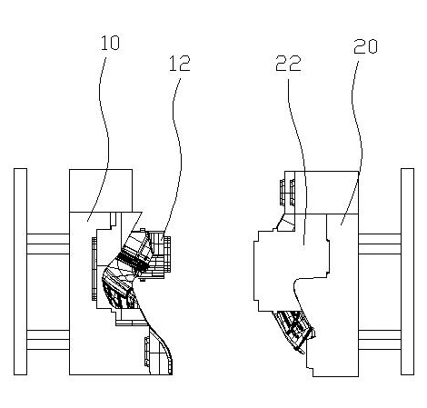
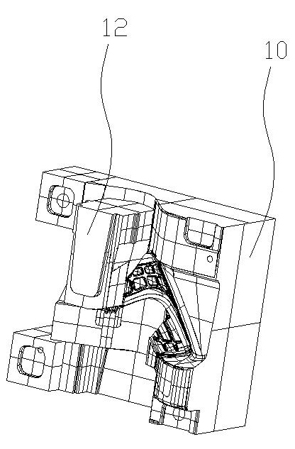
[0019] Below in conjunction with accompanying drawing and specific embodiment the present invention will be described in further detail: see Figure 1 ~ Figure 3 , the mold of special-shaped intake pipe, including first half mold 10 and second half mold 20, described first half mold 10 is provided with a first slide block 12, and described first slide block 12 can be relative to first half mold Die 10 slips. The position of the first slider 12 is the place where the diameter of the special-shaped intake pipe is smaller. Of course, the number of the first sliders 12 can be appropriately selected according to the shape of the special-shaped intake pipe.

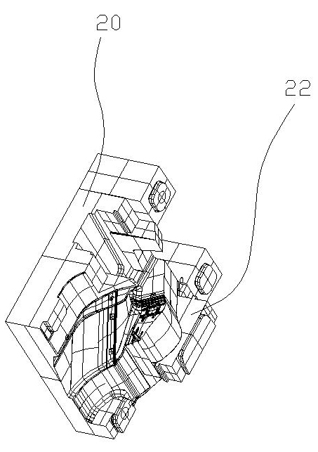
[0020] The second half-mould 20 is provided with a second slider 22 that can slide relative to the second half-mould 20 , and the two sliders can slide relative to the second half-mould 20 . Similarly, the position of the second slider 22 is also the place where the diameter of the special-shaped intake pipe is smaller. , th...


PUM


Abstract

The invention discloses a mold and a molding technology of a special-shaped inlet air pipe. The mold of the special-shaped inlet air pipe comprises a first mold half and a second mold half, wherein the first mold half is provided with a slide block, the second mold half is provided with a second slide block, and after the first mold half and the second mold half are combined together and the first slide block and the second slide block are combined together, a cavity formed by the first mold half, the first slide block, the second mold half and the second slide block is matched with the external surface of the special-shaped inlet air pipe. The molding technology comprises the following steps of: a) opening the mold; (b) extruding a blank to a mold cavity; c) combining the first mold half and the second mold half together; d) closing upper and lower sealing ports of the blank on the mold; e) respectively combining the first slide block and the second slide block together; f) blowing with a blow needle, and molding a product; g) opening the mold, and taking out the product. The mold and the molding technology can produce the special-shaped inlet air pipe through a two-dimensional blow molding method, and the produced special-shaped inlet air pipe is free of excess blanks and flashes.

Description

technical field [0001] The invention relates to a mold and a molding process for a special-shaped intake pipe. Background technique [0002] There are two types of blow molding process for pipe parts: 3D blow molding process: the mold is first clamped on the equipment, and the sealing device at the bottom of the mold is connected to the vacuum adsorption equipment. When the equipment is extruding the blank, the vacuum adsorption equipment works to vacuum the mold cavity. When the blank just falls into the mold cavity, it will be pulled by the vacuum generated by the vacuum adsorption equipment, and the blank passes through the mold cavity. When it reaches the lower seal of the mold, the upper and lower seals are closed at the same time, and the blowing needle is driven into the blank to blow air, and the product is formed. After the mold is released, since the blank enters the cavity when the mold is closed, there is no flash at the parting line of the product, and the pro...

Claims


Application Information

Patent Timeline
Patent Type & Authority Applications(China)
IPC IPC(8): B29C49/48B29C49/04
Inventor 沈国
Owner NINGBO JOYSONQUIN AUTOMOTIVE SYST HLDG CO LTD
Why Eureka
Try Eureka