A concrete grouting device for reinforced cages for buildings

A steel cage and concrete technology, which is applied in reinforcement molding, ceramic molding machines, manufacturing tools, etc., can solve the problems of local mortar accumulation, slow grouting speed, and influence on prefabrication effects, and achieve uniform feeding, fast feeding speed, and high feeding efficiency Effect

Active Publication Date: 2022-05-17
CHONGQING COLLEGE OF ELECTRONICS ENG
View PDF10 Cites 0 Cited by
  • Summary
  • Abstract
  • Description
  • Claims
  • Application Information

AI Technical Summary

Problems solved by technology

[0005] The object of the present invention is to provide a kind of concrete grouting device for steel cages for construction, to solve the problem that the existing prefabricated parts proposed in the above-mentioned background technology generally only grout the steel cages through a grouting pipe during processing, and the grouting speed is slow and at the same time Local mortar accumulation is easy to occur during grouting, which affects the prefabrication effect

Method used


Image

  • A concrete grouting device for reinforced cages for buildings
  • A concrete grouting device for reinforced cages for buildings
  • A concrete grouting device for reinforced cages for buildings

Examples


Embodiment Construction

[0048] The following will clearly and completely describe the technical solutions in the embodiments of the present invention with reference to the accompanying drawings in the embodiments of the present invention. Obviously, the described embodiments are only some, not all, embodiments of the present invention.

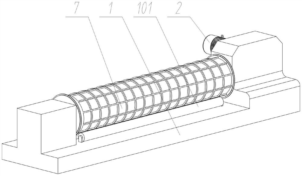
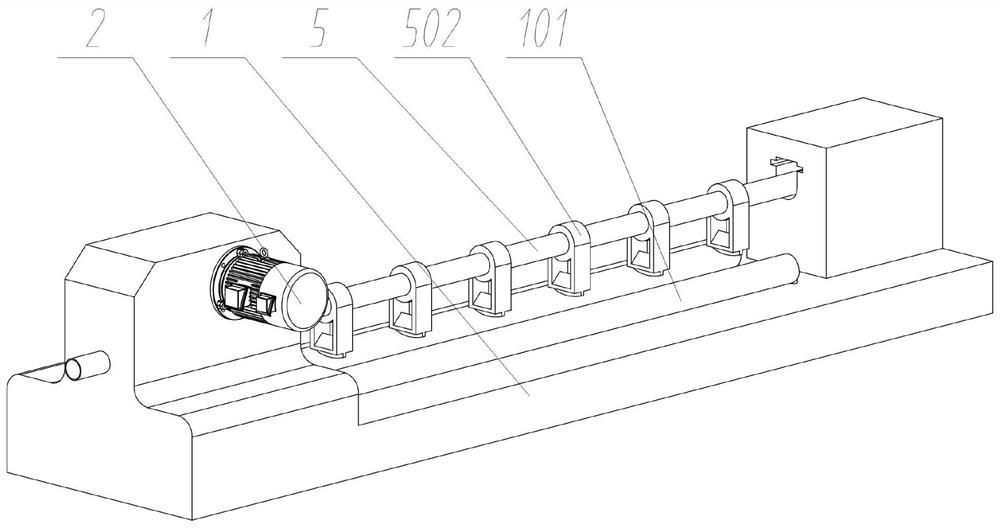
[0049] see Figure 1 to Figure 9 , an embodiment provided by the present invention: a reinforced cage concrete grouting device for construction, comprising a grouting main body 1;

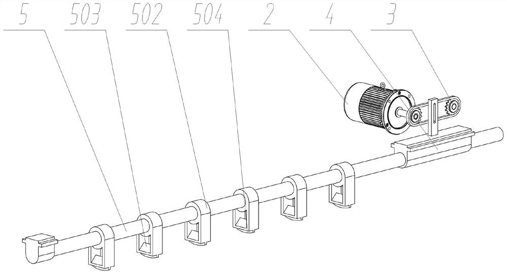
[0050] The grouting driving part 2 is fixedly installed on the right rear of the grouting main body 1;

[0051] The grouting transmission assembly 3 is installed inside the right side of the grouting main body 1, and the grouting transmission assembly 3 is composed of a filling sprocket 301, a filling transmission chain 302, and a filling lever 303, wherein a set of filling sprockets 301 and the grouting The rotating shaft of the driving member 2 is coaxially fixedly connected;

[0052]...


PUM


Abstract

The invention discloses a concrete grouting device for steel cages used in buildings, which relates to the technical field of building construction, and solves the problem that the existing prefabricated parts generally only use one grouting pipe to grout the steel cages during the processing process, the grouting speed is slow, and the grouting is performed at the same time. Local mortar accumulation is easy to occur in the process, which affects the prefabrication effect, including the grouting main body; the grouting driving part is fixedly installed on the right side of the grouting main body; the grouting transmission component is installed on the right side of the grouting main body, and the The grouting transmission assembly is composed of a filling sprocket, a filling transmission chain, and a filling lever, wherein one set of the filling sprocket is coaxially and fixedly connected with the rotating shaft of the grouting driving part. The invention has a fast feeding speed and improves feeding efficiency. At the same time, it realizes reciprocating sliding grouting feeding, effectively prevents material accumulation, and ensures uniform grouting. At the same time, the material distribution part and scraper plate further avoid effectively avoiding mortar accumulation and prevent the wall thickness of the prefabricated part. uneven problem.

Description

technical field [0001] The invention relates to the technical field of building construction, in particular to a reinforced cage concrete grouting device for building. Background technique [0002] Prefabricated concrete refers to concrete products processed and produced in the factory through standardized and mechanized methods. The corresponding traditional cast-in-place concrete requires on-site mold making, on-site pouring and on-site maintenance. Concrete prefabricated parts are widely used in construction, transportation In the field of water conservancy, water conservancy and other fields, it is necessary to make a reinforcement cage first during the processing of concrete prefabricated parts, then place the reinforcement cage into the mold, pre-tighten, and then grout. [0003] For example, application number: CN201210328326.8 The present invention discloses a mold system for building prefabricated parts and a prefabrication method thereof. The mold system includes a...

Claims


Application Information

Patent Timeline
Patent Type & Authority Patents(China)
IPC IPC(8): B28B21/30B28B21/32B28B21/60
CPCB28B13/02B28B21/68B28B23/02
Inventor 奚瑞
Owner CHONGQING COLLEGE OF ELECTRONICS ENG
Why Eureka
Try Eureka