Rotary vacuum device

A rotary, vacuum technology, applied in the field of mechanical structure, which can solve problems such as falling off, item displacement, and inability to fix lightweight items.

Inactive Publication Date: 2013-07-17
SUZHOU HUARI JINLING MACHINERY
View PDF4 Cites 0 Cited by
  • Summary
  • Abstract
  • Description
  • Claims
  • Application Information

AI Technical Summary

Problems solved by technology

[0002] At present, because the disc of the multi-position fixture cannot fix lightweight items such as paper pieces, thin sheets, etc. during the rotation process, the items often shift or fall off during the rotation.
Make it impossible to effectively implement automated production

Method used


Image

  • Rotary vacuum device

Examples


Embodiment Construction

[0016] The present invention will be described in detail below with reference to the accompanying drawings and in combination with embodiments.

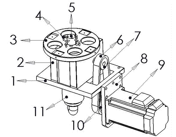
[0017] see figure 1 As shown, a rotary vacuum suction device includes a gap divider fixing plate 1 and a transmission motor plate 8, one side of the gap divider fixing plate 1 and the transmission motor plate 8 are fixed by screws, and the gap divider Gap divider 2 is fixed on the upper part of the device fixing plate 1, and a single-channel rotary joint 11 is fixed on the lower part. The pipeline type turntable 3 is directly locked on the flange of the gap divider 2, and the vacuum flange head 5 is fixed on the vacuum pipe 4. On the pipe-type turntable 3; the transmission motor plate 8 is provided with a transmission motor 9, the transmission motor 9 passes through the transmission motor plate 8 and is provided with a driving wheel 10, and the gap divider 2 is provided with a driven wheel 7. The driving wheel 10 is connected to the...


PUM


Abstract

The invention discloses a rotary vacuum intake device which comprises an interval slicer fixing plate and a transmission motor plate. One side of the interval slicer fixing plate and the transmission motor plate are fixed through screws, an interval slicer is fixed at the upper part of the interval slicer fixing plate, a single channel type rotary joint is fixed at the lower part of the interval slicer fixing plate, a pipeline type rotary table is directly locked on a flange of the interval slicer, a vacuum flange end is fixed to the pipeline type rotary table through a vacuum pipeline, the lower part of the vacuum flange end is connected with the single channel type rotary joint, the transmission motor plate is provided with a transmission motor, the transmission motor is provided with a driving wheel by penetrating through the transmission motor plate, the interval slicer is provided with a driven wheel, and the driving wheel is connected with the driven wheel through a transmission belt. In the rotary vacuum intake device, the single channel type rotary joint is adopted to transfer vacuum through the vacuum flange, and the vacuum is ingeniously clamped in a vacuum groove arranged on a disk so that a continuous vacuum pipeline is formed, a light and handy object placed on the disc work station can be normally absorbed by the vacuum, and accurate and stable functions are fulfilled.

Description

technical field [0001] The invention relates to the field of mechanical structures, in particular to a rotary vacuum device. Background technique [0002] At present, because the disc of the multi-position fixture cannot fix lightweight items such as paper sheets and thin sheets during the rotation process, the items often shift or fall off during the rotation. Make it impossible to effectively implement automated production. Contents of the invention [0003] The purpose of the present invention is to provide a rotary vacuum device, which uses a single-channel rotary joint to transmit vacuum through a vacuum flange, and cleverly clamps the vacuum into the built-in vacuum groove on the disc to achieve an uninterrupted vacuum tube. way, so that the light objects placed on the disc station can be normally sucked by vacuum to achieve precise and stable functions. [0004] In order to achieve the above-mentioned technical purpose and achieve the above-mentioned technical eff...

Claims


Application Information

Patent Timeline
Patent Type & Authority Patents(China)
IPC IPC(8): B65G47/91
Inventor 向延海
Owner SUZHOU HUARI JINLING MACHINERY
Why Eureka
Try Eureka