Contractible safety self-ruined syringe

A syringe and self-destruct technology, applied in the field of medical devices, can solve problems such as failure to use normally, low production yield, easy to fall off, etc.

Inactive Publication Date: 2006-05-24
邹志尚
View PDF1 Cites 0 Cited by
  • Summary
  • Abstract
  • Description
  • Claims
  • Application Information

AI Technical Summary

Problems solved by technology

The process of making the plug and piston of the above-mentioned syringe integrated is relatively difficult, the production yield is low, and the cost is high. When in use, due to the good elasticity of the rubber, the cut at the rear end of the plug is not easy to break, and it is difficult to achieve the plugging effect. ; If it is bonded, it is difficult to accurately locate the plug at the center of the piston, because the bonding area is small, so it is easy to fall off when not in use, and cannot be used normally

Method used


Image

  • Contractible safety self-ruined syringe
  • Contractible safety self-ruined syringe
  • Contractible safety self-ruined syringe

Examples


Embodiment 1

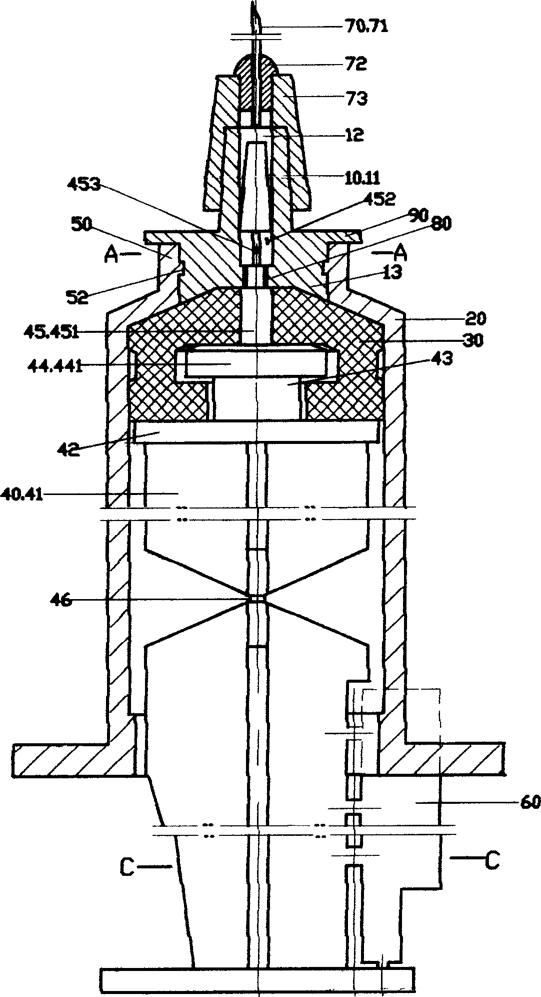
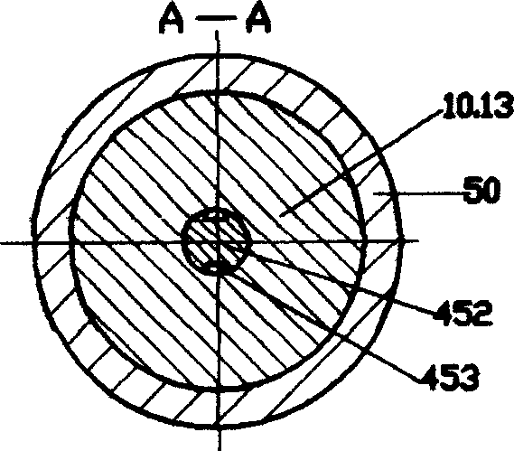
[0044] See figure 1 Referring to Fig. 8, the materials used in the syringe of this embodiment meet the national standard. The syringe of this embodiment comprises a jacket 20, a piston 30 and a core rod 40; the core rod 40 is an integral part with a shaft 41, a top 42, a neck 43 and a head 44; the piston 30 is sleeved on the head of the core rod 40 44, the syringe also has a retractable part 10, the retractable part 10 is an integral part with a cone head 11 and a positioning part 13, the positioning part 13 is arranged on the lower part of the retractable part 10, and the retractable part 10 has an axial through hole 12 The upper part of the overcoat 20 is provided with an airtight positioning part 50, the overcoat 20 and the airtight positioning part 50 are integrated, and the airtight positioning part 50 has a through hole 51; 51, the outer wall of the positioning part 13 of the retractable part 10 can be airtightly fitted with the inner wall of the through hole 51 of the ...

Embodiment 2

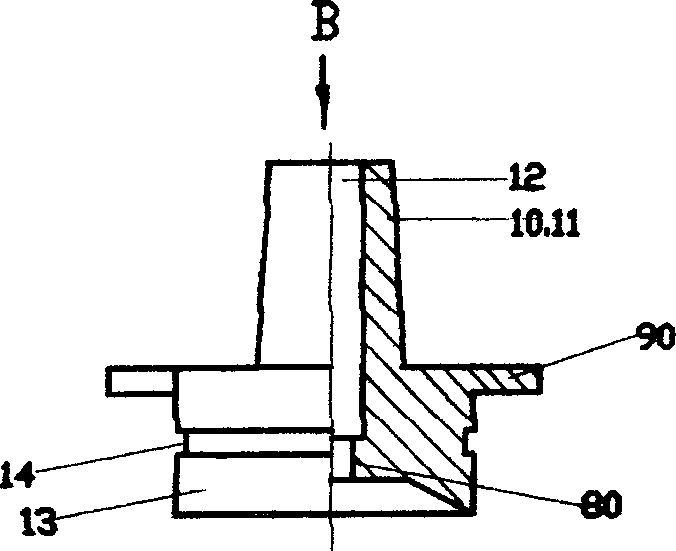
[0048] 9 to 12, the syringe of this embodiment is provided with a stopper 90 on the outer wall of the positioning part 13 of the retractable part 10; the stopper 90 is in the shape of a boss; the number of stoppers 90 in the shape of a boss It is one; in this embodiment, the size of the force that causes the retractable component 10 to disengage and shrink can be designed to be 35 Newtons, and the size of the outer diameter of the boss-shaped stopper 90 can be designed to be 35 Newtons. When the pulling force occurs, it will be disengaged and shrink; it can ensure the normal assembly of the syringe, and it can absorb and inject the liquid medicine normally during use; a sealing groove 53 is provided on the inner wall of the through hole 51 of the airtight positioning part 50 of the overcoat 20, so that The outer wall of the positioning portion 13 of the shrinkable component 10 is provided with a sealing boss 15, and the inner diameter of the sealing groove 53 on the inner wall ...

Embodiment 3

[0050] See Figure 13 to Figure 15 , the syringe of this embodiment is provided with an O-ring seal 131 on the outer wall of the positioning portion 13 of the retractable component 10; 131 is sleeved and fixed in the sealing groove 14 on the outer wall of the positioning portion 13 of the shrinkable part 10; a sealing groove 53 is provided on the inner wall of the through hole 51 of the airtight positioning portion 50 of the outer casing 20, and the O-ring seal The outer diameter of 131 is 0.25mm larger than the inner diameter of the sealing groove 53 on the inner wall of the through hole 51 of the airtight positioning part 50 of the outer casing 20, so as to achieve the purpose of strengthening the sealing effect and ensuring that the syringe can absorb and inject the liquid medicine normally. This embodiment is suitable for syringes with specifications below 20 milliliters. All the other are identical with embodiment 1.


PUM


Abstract

The present invention relates to a safety self-destructible type injector. It includes case shell, piston and core rod. Said core rod is an integrative component having rod body, top portion, neck portion and head portion, the piston is cover-mounted on the head portion of core rod. Said injector also has a retractable component, said retractable component is an integrative component having cone head and positioning portion. The positioning portion is placed in the lower portion of retractable component, and said retractable component has an axial through hole. Said invention also provides the concrete structure of its case shell, and also provides its operation method and concrete steps.

Description

technical field [0001] The invention relates to a safe self-destruction syringe, which belongs to the field of medical instruments. Background technique [0002] Chinese patent No. is 00219356.6, and the utility model patent description entitled "Blocking Type Disposable Syringe" discloses a syringe. The syringe includes a jacket, a core rod, and a piston; the jacket has a cone head, the cone head is provided with a cone head hole, and an annular boss is arranged in the cone head hole; the front end of the piston is provided with a plug, and the rear end of the plug has a cutout. There is a core bone in the center; the piston is connected with the plug, which can be made in one piece or bonded; the plug has a taper, and the front end is a small head; the inner wall of the annular boss is provided with at least one axial guide groove; A limit piece is provided at the rear of the rod. The process of making the plug and piston of the above-mentioned syringe integrated is rela...

Claims


Application Information

Patent Timeline
Patent Type & Authority Applications(China)
IPC IPC(8): A61M5/50
Inventor 邹志尚陈嘉农
Owner 邹志尚
Why Eureka
Try Eureka