Detachable support structure for clothes dryer

A support structure and technology for clothes dryers, which are applied in the directions of household clothes dryers, applications, household appliances, etc., can solve the problems of limited bending and torsional strength, unsightly reinforcement ribs, and reduced appearance aesthetics, etc. It is not easy to achieve The effect of storing dust, being easy to store in packaging and transportation, and reducing the volume of packaging

Active Publication Date: 2012-05-02
胡杰波
View PDF5 Cites 6 Cited by
  • Summary
  • Abstract
  • Description
  • Claims
  • Application Information

AI Technical Summary

Problems solved by technology

However, because the clothes rail has a notch, the overall strength of the clothes rail is relatively low. If the strength is to be increased, the rod must be thickened or ribs must be provided in the notch, which will result in an increase in the volume of the clothes rail and reduce the aesthetics of appearance; the second, such as Figure 1H , 1I As shown, the cross-section of the clothes rail is vertical or horizontal "H" shape, the advantage is that the processing mold is easy to form, but the torsional strength and overall strength of the clothes rail in the length direction are determined by the width and thickness of the sheet. Decision; if the piece is too thick, it will cause cooling shrinkage marks

Method used


Image

  • Detachable support structure for clothes dryer
  • Detachable support structure for clothes dryer
  • Detachable support structure for clothes dryer

Examples


Embodiment 1

[0046] Such as Figure 2A-2E Shown is a preferred embodiment of the present invention.

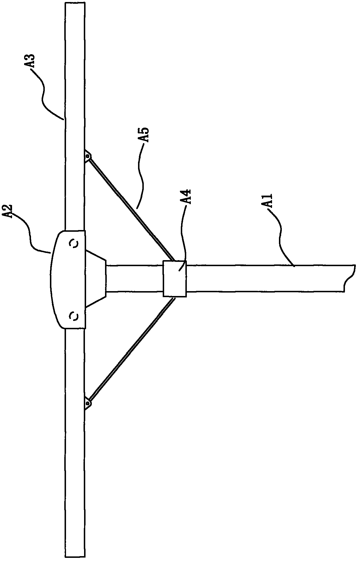
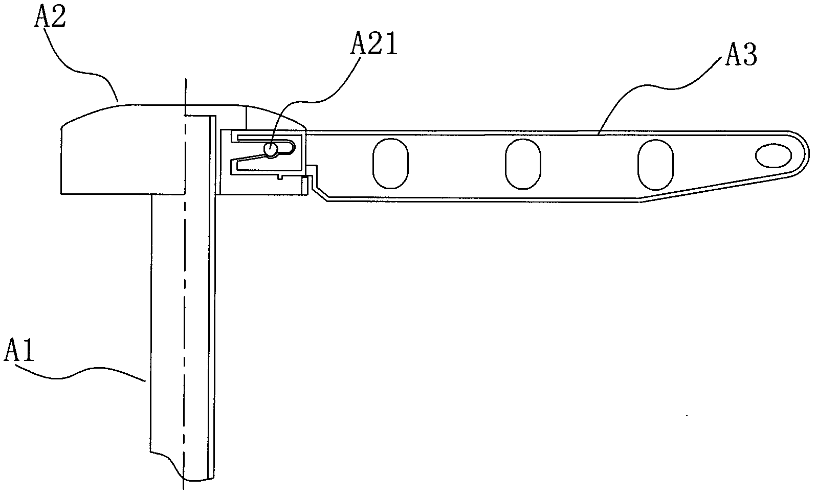
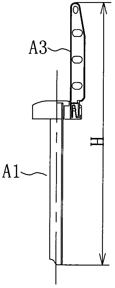
[0047] Figure 2A , 2B , 2C shows a detachable support structure applied to a shed-type clothes dryer. The detachable support structure includes a column with a diameter of 25mm and a bracket seat 2 fixed on the upper end of the column 1, which is fixed horizontally Multiple hanging arms 3 on the support base 2.

[0048] Among them, each hanging arm 3 is in a curved shape as a whole, including an upper surface 33, a lower surface 34, and two inner and outer end surfaces 35, 36. The upper surface 33 is provided with positioning for preventing the hanger from sliding on the hanging arm 3. In the groove 39, a connecting block 31 and a cone-shaped plunger 32 extending downward relative to the connecting block 31 are successively extended inward from the inner end surface 35. An upward integral extension is formed between the plunger 32 and the upper surface 33 The longitudinal sheet piece 37. Whe...

Embodiment 2

[0054] Such as Figure 3A , 3B This is the second embodiment of the present invention. The difference from the first embodiment is that the support structure further includes a locking member 5. The locking member 5 has a pressing head 51 and a screw part 52. Correspondingly, the bracket seat 2 A screw hole 28 matching the screw part 52 is provided at the center of the upper end surface of the screw. After fixing the hanging arm 3 and the bracket base 2, the screw part 52 is screwed into the bracket base 2 by rotating the pressing head 51 by hand, and the connecting block 31 inserted into the bracket base 2 and the inserting rod 32 are separated by the pressing head 51 Press it from above to prevent it from coming out of the socket 21 of the bracket base 2 upward.

[0055] Of course, furthermore, a threaded hole 11 matching the screw part 52 can also be provided at the upper end of the corresponding column 1. First insert the column 1 into the sleeve 25 so that the screw hole 28...

Embodiment 3

[0058] Such as Figure 4A Shown is the third embodiment of the present invention. The difference from the first embodiment is that it further includes a bracket cover 4, the upper surface of the bracket cover 4 is a spherical surface, which is fixed to the bracket by screws or other detachable methods. The upper part of the seat 2 is used to cover the inserting rod 32 and the connecting block 31 from above after the connecting block 31 and the inserting rod 32 of the hanging arm 3 are inserted into the support base 2, and the connecting block 31 and the inserting rod 32 are sealed in the support base 2 and the support Between the covers 4, the appearance is more beautiful.

[0059] It is worth noting that such as Figure 4B As shown, preferably, the bracket cover 4 and the locking member 5 are combined into an integral structure, and the pressing head 51 of the locking member 5 is the bracket cover 4, and the upper surface of the pressing head 51 is a spherical surface.


PUM


Abstract

The invention relates to a detachable support structure for a shed type clothes dryer. The detachable support structure comprises an upright post, a support seat fixed on the upper end of the upright post and at least one hanging arm laterally arranged on the support seat, wherein at least one plug hole is arranged on the upper end surface of the support seat from top to bottom; open slots communicated with each plug hole are arranged at the position, corresponding to each plug hole, on the external surface of the support seat from the upper end surface to bottom; at least one connection block, which is matched with the open slots, and insert rods, which extend vertically downwards relative to the hanging arms and are matched with the plug holes, integrally and sequentially extend on the internal ends of the hanging arms; and the hanging arms are downward inserted into the plug holes and the open slots through the connection blocks and insert rods at the internal ends. According to the support provided by the invention, the volume of the support seat is reduced, the detaching of the entire support is facilitated and the support is convenient for storage, package and transport. Theentire support has a full rod-shaped external surface and hollow inside, thus the strength of the hanging arms is guaranteed, the hanging arms have smooth surface, the structure is contributed to being held by a user, and the surface has small possibility of generating dust.

Description

Technical field [0001] The invention relates to a support structure, in particular to a detachable support structure for a shed-type clothes dryer. Background technique [0002] The bracket structure of the traditional shed-type clothes dryer consists of a column, a support seat fixed at the upper end of the column, one end supported by the support seat, and a clothes rail extending laterally at the other end. In order to reduce the storage volume, the clothes rail is required to be made Can be folded. [0003] Such as Figure 1A Shown here is an existing umbrella support structure. The support structure includes a column A1, a support seat A2 fixed on the upper end of the column A1, and a clothes rail A3 pivotally connected to the support seat A2 at one end, sleeved under the support seat A2 One end of the sliding seat A4 on the column A1 is pivotally connected to the sliding seat A4, and the other end is pivotally connected to the pull rod A5 in the middle section of the clothes ...

Claims


Application Information

Patent Timeline
IPC IPC(8): D06F58/00D06F58/20
Inventor 胡杰波
Owner 胡杰波
Why Eureka
Try Eureka