Mechanical hydraulic composite continuously variable transmission of engineering vehicle with brake energy recovering function

A technology of braking energy recovery and continuously variable transmission, which is applied in mechanical equipment, transmission devices, fluid transmission devices, etc., can solve problems such as large load changes, loss of mechanical inertia, and no energy recovery function of vehicles, so as to improve power performance, The effect of stepless speed regulation mechanical transmission

Inactive Publication Date: 2012-05-02
SOUTHWEST JIAOTONG UNIV
View PDF6 Cites 20 Cited by
  • Summary
  • Abstract
  • Description
  • Claims
  • Application Information

AI Technical Summary

Problems solved by technology

Due to the harsh working environment of engineering vehicles, large load changes, and changing working conditions, a gearbox must be used to adapt to this change. Traditional mechanical transmission and hydraulic transmission gearboxes have their own advantages and limitations.
[0003] In addition, some engineering vehicles (such as tractors, excavators, loaders, etc.) need to perform frequent braking during the working process. Almost all of the current vehicles have no energy recovery function, and the energy generated by mechanical inertia during the braking process is lost. up

Method used


Image

  • Mechanical hydraulic composite continuously variable transmission of engineering vehicle with brake energy recovering function
  • Mechanical hydraulic composite continuously variable transmission of engineering vehicle with brake energy recovering function

Examples


Embodiment

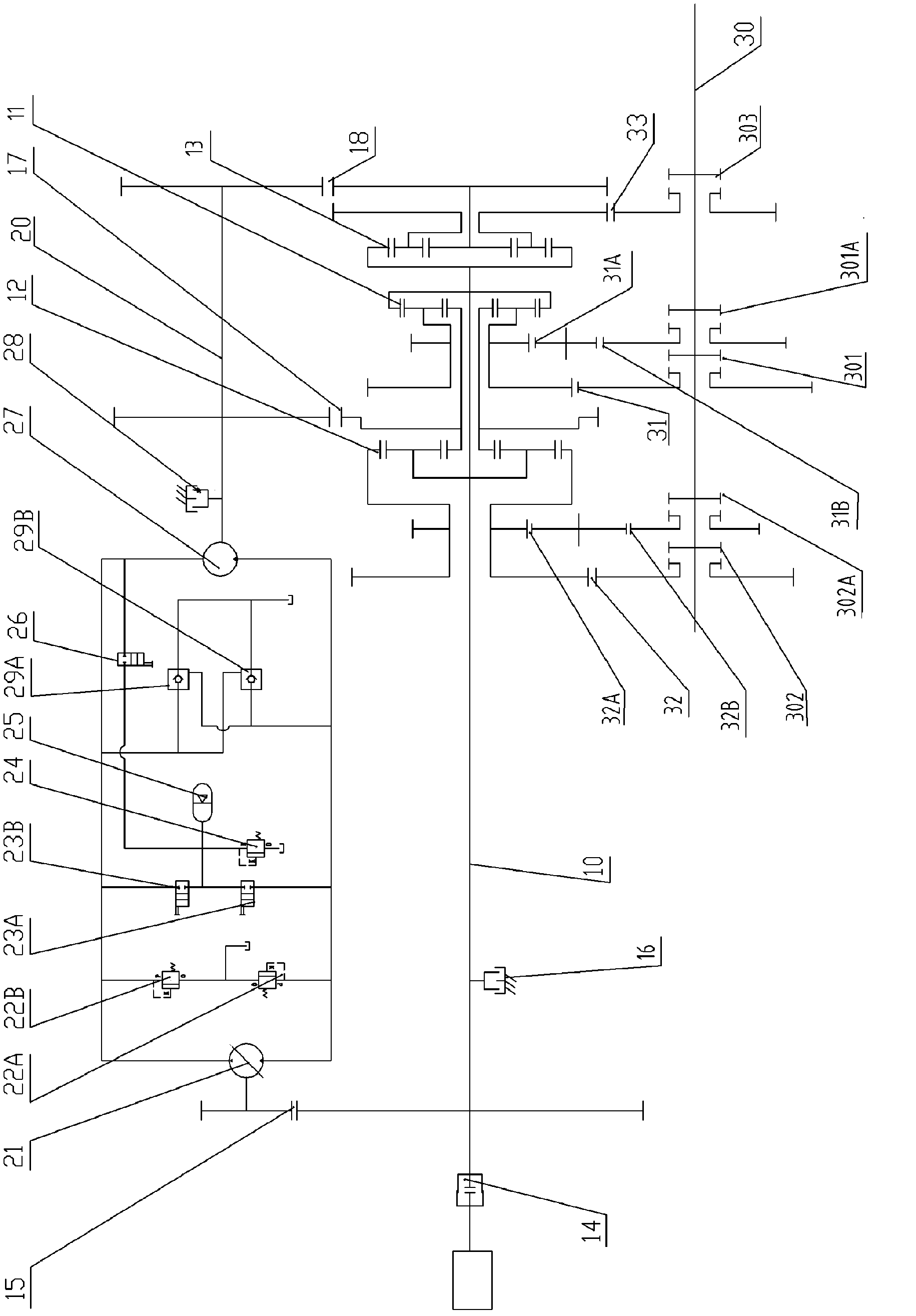
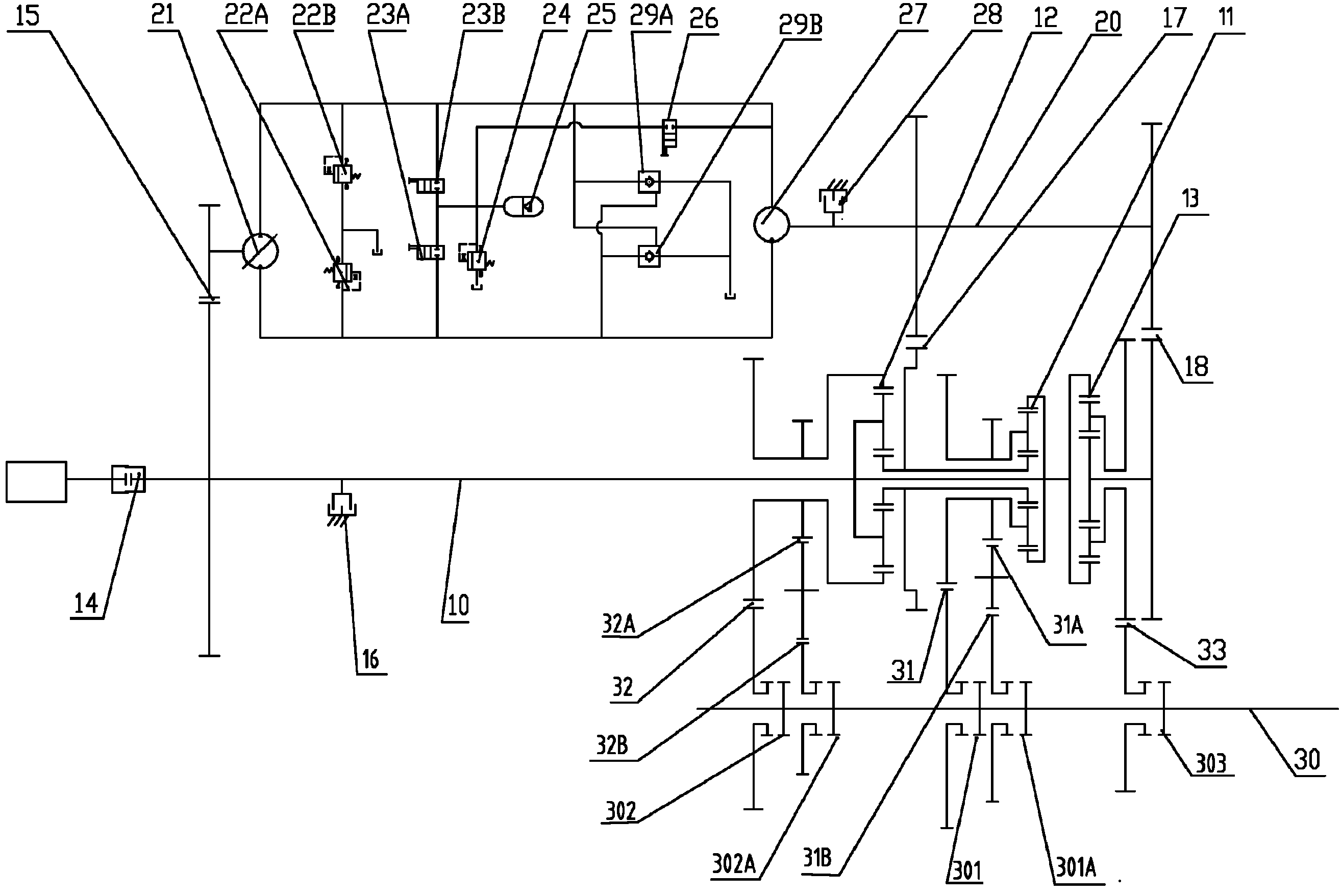
[0026] figure 1 It is shown that a specific embodiment of the present invention is a mechanical-hydraulic compound continuously variable transmission for engineering vehicles with a braking energy recovery function, including a clutch 14, a brake 16, a planetary row 11, a Planetary row two 12, planetary row three 13, multiple fixed shaft gear sets connected with the three planetary rows 11, 12, 13, and multiple clutches on the output shaft 30, wherein:

[0027] The input shaft 10 is provided with a mechanical-hydraulic linkage fixed-axis gear set 15, and one end of the driven shaft of the mechanical-hydraulic linkage fixed-axis gear set 15 is provided with a hydraulic variable pump 21, and the two ends of the hydraulic variable pump 21 are connected with the two ends of the hydraulic motor 27 Constitute a hydraulic circuit; the two ends of the hydraulic variable pump 21 are respectively connected with a relief valve 1 22A, a relief valve 2 22B, a reversing valve 23A, a reversi...


PUM


Abstract

The invention discloses a mechanical hydraulic composite continuously variable transmission of an engineering vehicle with a brake energy recovering function. An input shaft is provided with a mechanical hydraulic linked fixed shaft gear set. A hydraulic variable pump is arranged at one end of the driven shaft of the gear set. Two ends of the hydraulic variable pump are connected with two ends of a hydraulic motor to form a hydraulic loop. Two ends of the hydraulic variable pump are connected with a first overflowing valve, a second overflowing valve, a first reversing valve and a second reversing valve. An energy accumulator is arranged between the first reversing valve and the second reversing valve. One end of a first one-way valve and a second one-way valve is connected with an oil tank while the other end of the first one-way valve and the second one-way valve is connected with the hydraulic loop of the hydraulic variable pump and the hydraulic motor. An output shaft of the hydraulic motor is provided with a first auxiliary fixed shaft gear set and a second auxiliary fixed shaft gear set. The first auxiliary fixed shaft gear set is connected with a first planet row and a second planet row on the input shaft. The second auxiliary fixed shaft gear set is connected with a third planet row on the input shaft. The output shaft of the hydraulic motor is further provided with a brake. The mechanical hydraulic composite continuously variable transmission integrates high efficiency characteristics of hydraulic transmission stepless speed regulation and mechanical transmission, and can also recover energy and save energy.

Description

technical field [0001] The invention relates to a transmission of an engineering vehicle. Background technique [0002] Engineering vehicles such as excavators, loaders, bulldozers, and tractors are widely used in various fields of social construction, and play an important role in improving operation speed and quality, reducing labor intensity, and reducing engineering costs. Due to the harsh working environment of engineering vehicles, large load changes, and changing working conditions, a gearbox must be equipped to adapt to this change. Traditional mechanical transmission and hydraulic transmission gearboxes have their own advantages and limitations. [0003] In addition, some engineering vehicles (such as tractors, excavators, loaders, etc.) need to perform frequent braking during the working process. Almost all of the current vehicles have no energy recovery function, and the energy generated by mechanical inertia during the braking process is lost. up. Contents of ...

Claims


Application Information

Patent Timeline
Patent Type & Authority Applications(China)
IPC IPC(8): F16H47/04
Inventor 刘桓龙于兰英王国志柯坚吴文海
Owner SOUTHWEST JIAOTONG UNIV
Why Eureka
Try Eureka