

Signal processing method of automatic zero-point electromagnetic flow meter system thereof
An electromagnetic flowmeter and signal processing technology, applied in the application of electromagnetic flowmeter to detect fluid flow, volume/mass flow generated by electromagnetic effect, and measure flow/mass flow, etc. Correction, performance improvement effect
- Summary
- Abstract
- Description
- Claims
- Application Information
AI Technical Summary
Problems solved by technology
Method used
Image

Examples
Embodiment 1
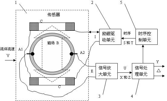
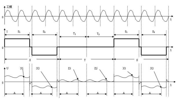
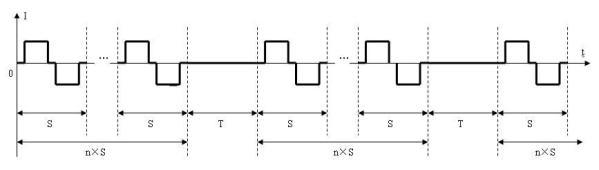
[0024] see figure 1 , the electromagnetic flowmeter signal processing method of automatic zero point, the processing system that adopts comprises a sensor 1, an excitation drive unit 2, a signal amplification unit 3, a signal processing unit 4 and a sequence control unit 5; Make described excitation drive unit 2 Output the excitation current I according to the timing S of the timing control unit 5 to generate an excitation magnetic field B in the sensor 1; the measured fluid with a flow velocity V flows through the sensor 1 so that the sensor 1 outputs an induced potential signal E, and the signal amplification unit 3 After the induced potential signal E is amplified, the signal U=X is output, and the value of the signal U=X is collected by the signal processing unit 4 to estimate the value of the fluid velocity V flowing through the sensor 1; it is characterized in that the timing S of the timing control unit 5 In this working period T, the excitation current I=0 of the excit...
Embodiment 2
[0029] see figure 1 , the automatic zero point electromagnetic flowmeter signal processing system, used for the above automatic zero point electromagnetic flowmeter signal processing method, including a sensor 1, an excitation drive unit 2, a signal amplification unit 3, a signal processing unit 4 and a sequence control unit 5. The output of the sensor 1 is output to the signal processing unit 4 after the signal amplifying unit 3, and the signal processing unit 4 is connected to the excitation driving unit 2 through the timing control unit 5, and the excitation driving unit 2 Outputting the excitation current I causes the excitation magnetic field B to be generated in the sensor 1; the timing control unit 5 outputs the timing S so that the excitation drive unit 2 is divided into working periods S 1 and S 2 Use I=I respectively 1 The constant current sum with I=I 2 =- I 1 The constant current works in the forward and reverse constant current excitation mode, so that the fo...
PUM
 Abstract
Description
Claims
Application Information