
Forced isotropic turbulence experimental apparatus

An experimental device and isotropic technology, applied in the direction of measuring device, fluid dynamics test, instrument, etc., can solve the problems of complex experimental system, inconvenient measurement, inability to use liquid experiment, etc., and achieve simple experimental system, simple structure, small size effect

Active Publication Date: 2013-11-20
HARBIN INST OF TECH
View PDF6 Cites 2 Cited by
  • Summary
  • Abstract
  • Description
  • Claims
  • Application Information

AI Technical Summary

Problems solved by technology

[0003] The purpose of the present invention is to solve the problems of complex experimental system, inconvenient measurement and inability to be used in liquid experiments in existing experimental devices, and to provide a forced isotropic turbulent flow experimental device

Method used


Image

  • Forced isotropic turbulence experimental apparatus

Examples


specific Embodiment approach 1

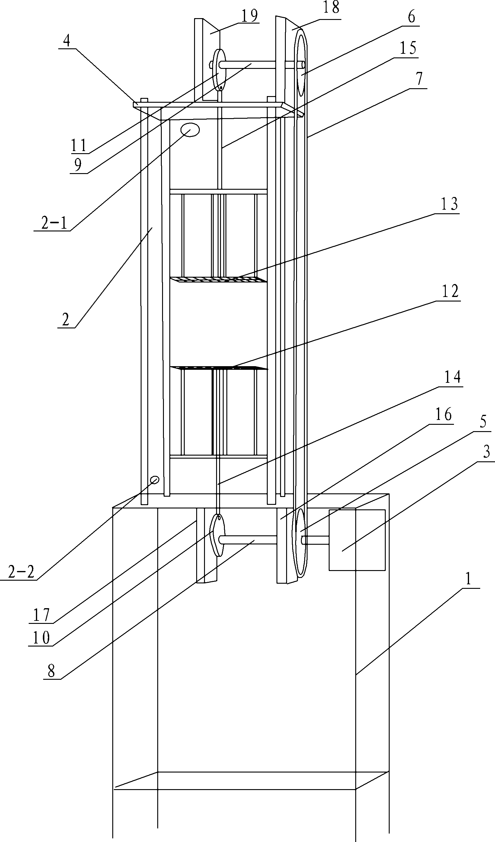
[0007] Specific implementation mode one: combine figure 1 Describe this embodiment, a kind of forced isotropic turbulence experiment device of this embodiment comprises chassis 1 and water tank 2, and water tank 2 is arranged on chassis 1, described forced isotropy turbulence experiment device also comprises motor 3, support Frame 4, first pulley 5, second pulley 6, synchronous belt 7, first drive shaft 8, second drive shaft 9, first eccentric cam 10, second eccentric cam 11, first mesh 12, second mesh Grid 13, the first connecting rod 14, the second connecting rod 15, the first support plate 16, the second support plate 17, the third support plate 18 and the fourth support plate 19, the support frame 4 is arranged on the water tank 2, the water tank 2 The upper part of the outer wall of the water tank 2 is provided with a water inlet 2-1, and the lower part of the outer wall of the water tank 2 is provided with a water outlet 2-2. and the fourth support plate 19 are arranged...

specific Embodiment approach 2

[0009] Specific implementation mode two: combination figure 1 Describe this embodiment, the water tank 3 of this embodiment is a plexiglass water tank. In this way, the water tank is made of transparent plexiglass, which is convenient for observation. Advanced laser Doppler velocimeter and particle image velocimeter and other experimental instruments are used to force the fluid in the water tank to be isotropic without affecting the flow field. To observe and measure turbulence phenomena. Other compositions and connections are the same as in the first embodiment.

specific Embodiment approach 3

[0010] Specific implementation mode three: combination figure 1 The present embodiment will be described. The grid 5 of the present embodiment is square, and a plurality of square turbulence ports are opened on the grid 5 . Such setting facilitates the realization and completion of the experimental phenomenon of forced isotropic turbulent flow. Other compositions and connections are the same as those in Embodiment 1 or Embodiment 2.


PUM


Abstract

The invention provides a forced isotropic turbulence experimental apparatus, which relates to a turbulence experimental apparatus and solves the problem that the existing experimental apparatus has a complex experimental system, is inconvenient for measurement and cannot be used in liquid experiments. A motor of the forced isotropic turbulence experimental apparatus is arranged at the bottom end of a chassis; a first pulley is arranged on a first support plate; a second pulley is arranged on a third support plate; the first pulley is connected with the second pulley through a synchronous belt; a first eccentric cam is eccentrically arranged on a first transmission shaft in a penetrating way; one end of a first connecting rod is connected with a first grid, and the other end of the first connecting rod passes through a water box to be rotationally connected with the first eccentric cam; a second eccentric cam is eccentrically arranged on a second transmission shaft in a penetrating way; and one end of a second connecting rod is connected with a second grid, and the other end of the second connecting rod passes through the water box to be rotationally connected with the second eccentric cam. The forced isotropic turbulence experimental apparatus is suitable for being used in a forced isotropic turbulence experiment.

Description

technical field [0001] The invention relates to a turbulence experiment device, in particular to a forced isotropic turbulence experiment device. Background technique [0002] Isotropic turbulent flow is the simplest turbulent flow, and it is the easiest to carry out theoretical analysis, experimental research and numerical simulation. By setting one or several rows of regular grids in the uniform airflow of the wind tunnel test section, irregular disturbances are generated when the uniform airflow passes through the grids vertically. As this irregular disturbance moves downstream, it gradually evolves into isotropic turbulent flow because there is no external disturbance. After the flow distance is greater than 30 to 40 times the grid scale, the turbulence in the uniform airflow in the central area of ​​the wind tunnel test section is close to isotropy. The flow behind the grid can be divided into three typical regions: (1) grid turbulence formation area; (2) grid turbule...

Claims


Application Information

Patent Timeline
Patent Type & Authority Patents(China)
IPC IPC(8): G01M10/00
Inventor 蔡伟华李凤臣张红娜李小斌徐鸿鹏阳倦成
Owner HARBIN INST OF TECH
Learn More