Working method of medium loss current tester

A technology of dielectric loss and working method, applied in instruments, measuring devices, measuring electrical variables, etc., can solve the problems of unreliability, short-range leakage, and low accuracy of analysis results, and achieve the effect of simple algorithm and easy implementation

Active Publication Date: 2012-05-02
内蒙古华测电力科技有限公司
View PDF2 Cites 21 Cited by
  • Summary
  • Abstract
  • Description
  • Claims
  • Application Information

AI Technical Summary

Problems solved by technology

[0007] In engineering applications, harmonic analysis always carries out limited point sampling and it is difficult to achieve strict synchronous sampling
In this way, when quasi-synchronous DFT is used for harmonic analysis, there will be long-range leakage due to the truncation effect and short-range leakage due to the fence effect, making the analysis results inaccurate and even unreliable

Method used


Image

  • Working method of medium loss current tester
  • Working method of medium loss current tester

Examples


Embodiment Construction

[0042] The dielectric loss current tester of the present embodiment consists of a CPU (using a single-chip microcomputer C8051F040), a signal sampling circuit connected to the CPU (using an AC data acquisition chip MAX197), a power supply module for providing AC power to the tested piece, and It consists of an LCD display unit connected to the CPU.

[0043] As the control core of the dielectric loss current tester, the CPU is used to control the frequency of the AC output of the power module, and to control sampling and process the sampling data. The third is to send display data to the display module; the power supply module produces a high-voltage sine wave with the same output frequency as the CPU; the signal sampling circuit is controlled by the CPU to collect data; the LCD display unit displays the data processing results of the CPU.

[0044] The working method of the dielectric loss current tester of the present embodiment comprises the following steps:

[0045] First, ...


PUM


Abstract

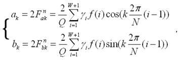
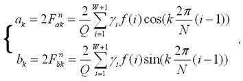
The invention discloses a working method of an improved high precision medium loss current tester based on quasi-synchronization DFT. The method comprises the following steps: simultaneously sampling a voltage signal V and a current signal I which are applied on a tested piece; applying variable fence quasi-synchronization DFT harmonic wave analysis technology to obtain a fundamental wave phase angle of applied voltage; applying the variable fence quasi-synchronization DFT harmonic wave analysis technology to obtain a fundamental wave initial phase angle of the current signal; calculating dielectric loss tangent according to a formula. According to the working method, an analysis error of the quasi-synchronization DFT harmonic wave analysis technology is effectively improved, a harmonic wave analysis result with high precision is obtained, and reliability of a medium loss current test is raised.

Description

technical field [0001] The invention relates to a working method of a high-precision dielectric loss current tester. Background technique [0002] The intelligent dielectric loss tester is an automatic instrument for measuring the dielectric loss tangent and capacitance value. It can measure various insulating materials, insulating bushings, power cables, capacitors, transformers, transformers and other high-voltage equipment on site under power frequency and high voltage. Dielectric loss tangent and capacitance value. The instrument is also suitable for measuring the dielectric loss tangent and capacitance value of high-voltage electrical equipment in workshops, laboratories, and scientific research units; it is equipped with an insulating oil cup to test the dielectric loss of insulating oil. [0003] The working principle of the intelligent dielectric loss tester: when an AC voltage is applied to the dielectric, there is a phase angle difference between the voltage and t...

Claims


Application Information

Patent Timeline
Patent Type & Authority Applications(China)
IPC IPC(8): G01R27/26
Inventor 傅中君侯雪亚
Owner 内蒙古华测电力科技有限公司
Why Eureka
Try Eureka