Image processing apparatus and image processing method

An image processing device and object image technology, applied in the field of image processing, can solve the problems of inability to properly detect contour edges, multiple edge lines, etc.

Inactive Publication Date: 2012-05-02
OLYMPUS CORP
View PDF5 Cites 17 Cited by
  • Summary
  • Abstract
  • Description
  • Claims
  • Application Information

AI Technical Summary

Problems solved by technology

However, as for the outline part where there is a gentle gradient in the middle of one gradient, the peak position of the distribution of the gradient intensity is divided into two or more, so in the above-mentioned J.Canny, A Computational Approach to Edge Detection, IEEE Trans.On Pattern Analysis and Machine Intelligence, 8(6), pp.679-698, 1986 and Japanese Patent Application Laid-Open No. 2007-140684, such as the existing edge detection processing, there will be a problem that multiple edge lines are detected near the contour
In addition, in the technology of Japanese Patent Application Laid-Open No. 7-225847, the detection result of the contour edge is affected by the setting method of the thick contour line, so sometimes the contour edge of the object cannot be detected properly.

Method used


Image

  • Image processing apparatus and image processing method
  • Image processing apparatus and image processing method
  • Image processing apparatus and image processing method

Examples


no. 1 Embodiment approach

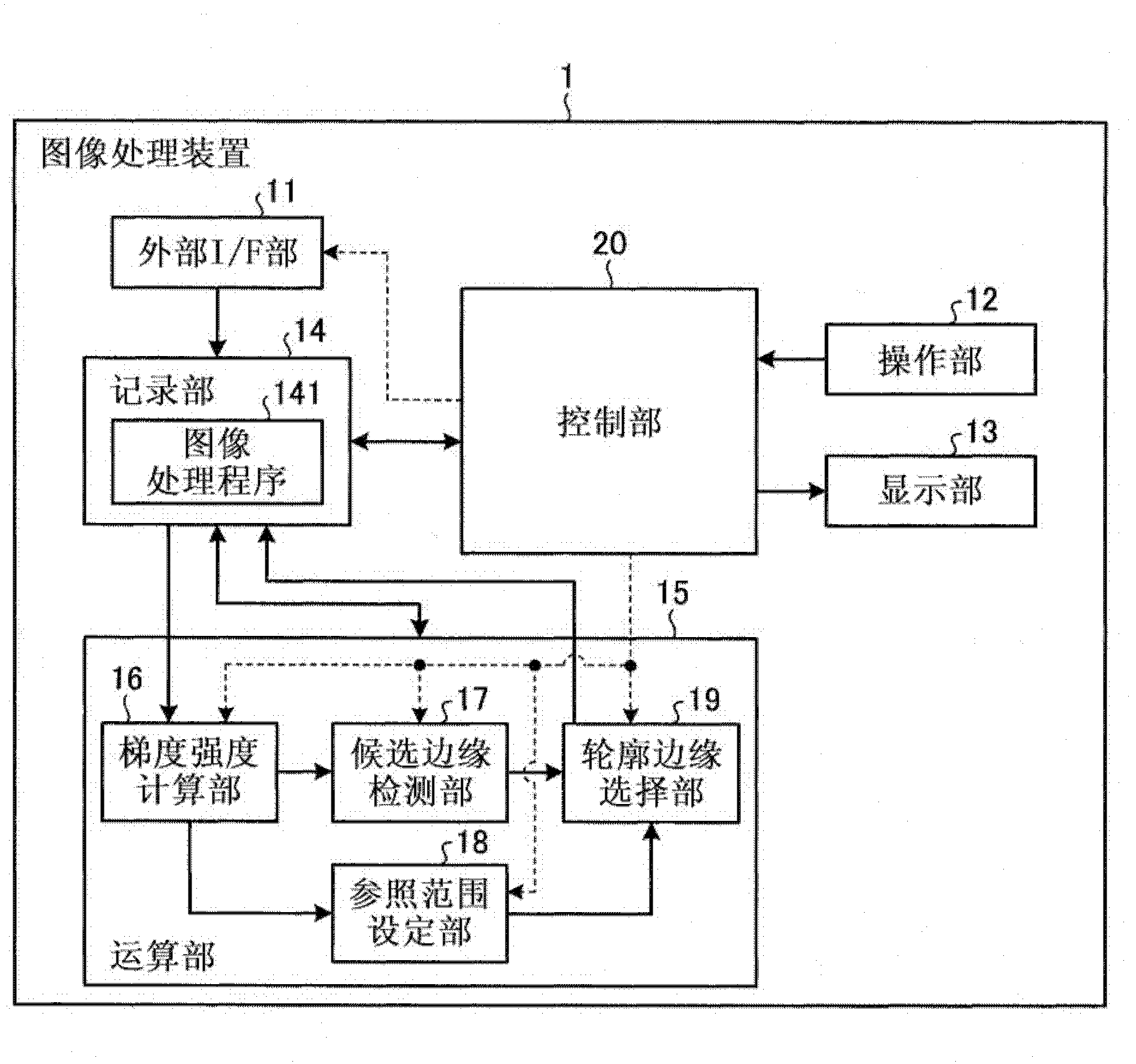
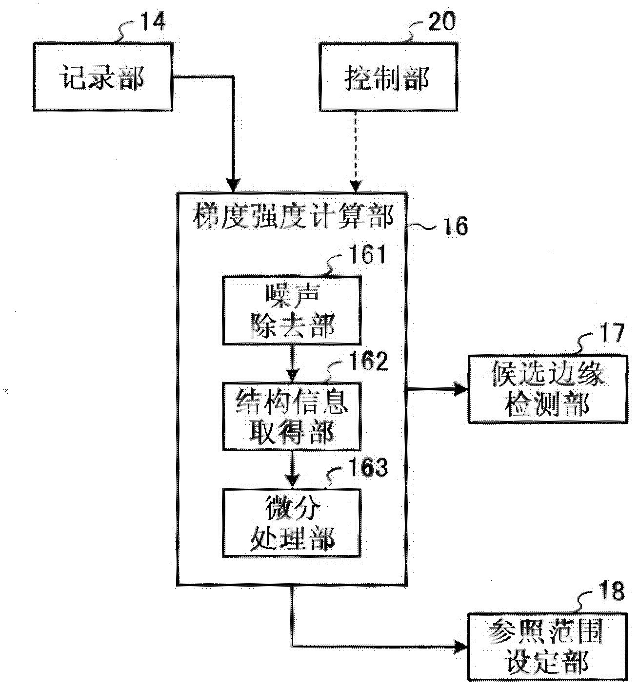
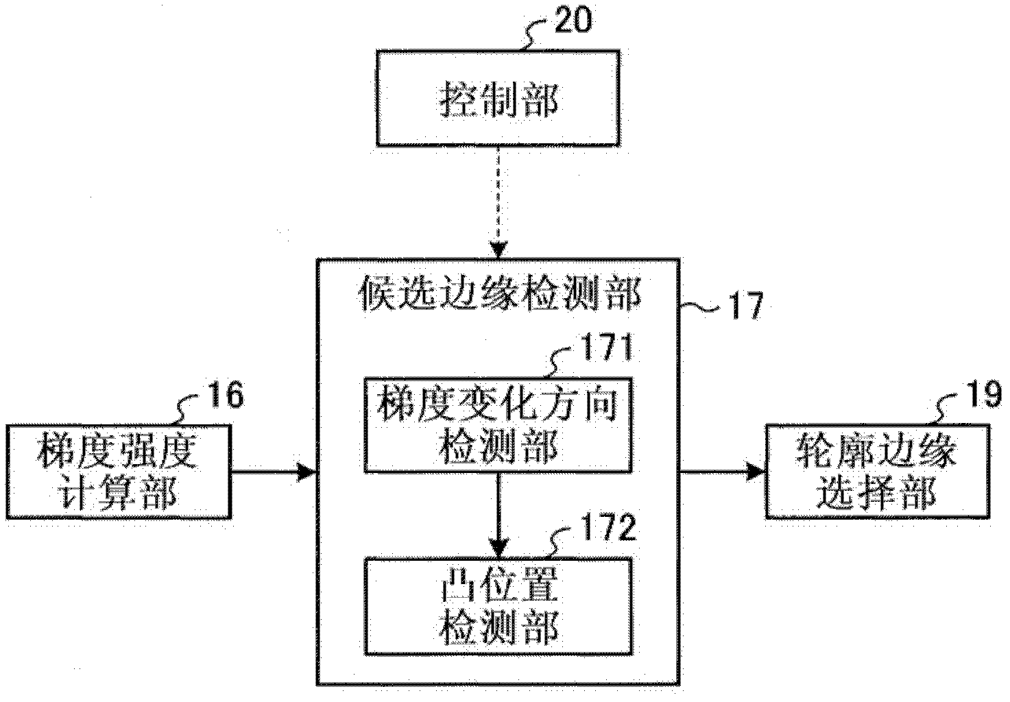
[0056] First, the image processing apparatus of the first embodiment will be described. figure 1 It is a block diagram explaining a functional configuration example of the image processing apparatus 1 of the first embodiment. In addition, figure 2 It is a block diagram illustrating a configuration example of the gradient intensity calculation unit 16 of the first embodiment constituting the calculation unit 15, image 3 It is a block diagram illustrating a configuration example of the candidate edge detection unit 17 of the first embodiment. Figure 4 It is a block diagram illustrating a configuration example of the reference range setting unit 18 of the first embodiment, Figure 5 It is a block diagram explaining a configuration example of the contour edge selection unit 19 of the first embodiment. And, in Figure 1 ~ Figure 5 In each of the figures, solid lines indicate data signal lines that connect the various parts of the image processing apparatus 1 to transmit data signal...

no. 2 Embodiment approach

[0135] First, the structure of the image processing apparatus of the second embodiment will be described. Figure 27 It is a block diagram explaining a functional configuration example of the image processing device 1a of the second embodiment. In addition, Figure 28 It is a block diagram illustrating a configuration example of the candidate edge detection unit 17a constituting the calculation unit 15a, Figure 29 It is a block diagram illustrating a configuration example of the reference range setting unit 18a, Figure 30 It is a block diagram explaining a configuration example of the contour edge selection unit 19a. In addition, the same reference numerals are given to the same structures as those described in the first embodiment. Such as Figure 27 As shown, the image processing apparatus 1a of the second embodiment includes an external I / F unit 11, an operation unit 12, a display unit 13, a recording unit 14a, a computing unit 15a, and a control unit 20 that controls the o...

no. 3 Embodiment approach

[0161] First, the structure of the image processing apparatus of the third embodiment will be described. Figure 35 It is a block diagram illustrating a functional configuration example of the image processing apparatus 1b of the third embodiment. In addition, the same reference numerals are given to the same structures as those described in the first embodiment. Such as Figure 35 As shown, the image processing apparatus 1b of the third embodiment includes an external I / F unit 11, an operation unit 12, a display unit 13, a recording unit 14b, a calculation unit 15b, and a control unit 20 that controls the overall operation of the image processing apparatus 1b.

[0162] The recording unit 14b records an image processing program 141b for realizing the processing of the third embodiment and detecting contour edges (contour edges of the mucosal structure) from the image inside the lumen.

[0163] In addition, the calculation unit 15b includes the gradient intensity calculation unit 16...


PUM


Abstract

An image processing apparatus includes a gradient magnitude calculating unit that calculates a gradient magnitude of each pixel on the basis of pixel values of a target image in which a predetermined target object is imaged; a candidate-edge detecting unit that detects contour-candidate edge positions on the basis of the gradient magnitude of each pixel; a reference-range setting unit that sets a reference range, which is to be referred to when a contour edge position is selected from among the contour-candidate edge positions, on the basis of the gradient magnitude of each pixel; and a contour-edge selecting unit that selects, as the contour edge position, one of the contour-candidate edge positions in the reference range.

Description

Technical field [0001] The present invention relates to an image processing device and an image processing method for detecting the contour edge of an object based on an object image. Background technique [0002] Generally, edge detection in an image is performed by detecting a position with a large gradient change. Basically, the gradient intensity is calculated according to the gradient of the brightness value of the image, and the detection is performed by thresholding the gradient intensity. Regarding specific methods, various solutions have been proposed. As one of them, for example, the Canny edge detection algorithm is known (see Canny edge detector, J. Canny, A Computational Approach to Edge Detection, IEEE Trans. On Pattern Analysis and Machine Intelligence, 8(6), pp. 679-698, 1986). In addition, Japanese Patent Application Laid-Open No. 2007-140684 discloses a method of detecting edges while suppressing noise edges. In the Japanese Patent Laid-Open No. 2007-140684, t...

Claims


Application Information

Patent Timeline
Patent Type & Authority Applications(China)
IPC IPC(8): G06T7/00
CPCG06T7/0085G06T2207/10068G06T2207/20148G06T2207/20136G06T7/13G06T7/181G06T7/136
Inventor 河野隆志神田大和北村诚松田岳博弘田昌士
Owner OLYMPUS CORP
Why Eureka
Try Eureka