Push switch and method for manufacturing the same

A manufacturing method and switch technology, applied in electrical switches, contact with individual bridge contacts, electrical components, etc., can solve problems such as weak adhesion

Inactive Publication Date: 2012-05-02
PANASONIC CORP
View PDF4 Cites 17 Cited by
  • Summary
  • Abstract
  • Description
  • Claims
  • Application Information

AI Technical Summary

Problems solved by technology

Therefore, when the pressing operation is repeated, the adhesive force becomes weak, and there is a problem that the protective sheet 7 and the storage member 11 are peeled off.

Method used


Image

  • Push switch and method for manufacturing the same
  • Push switch and method for manufacturing the same
  • Push switch and method for manufacturing the same

Examples


Embodiment approach 1

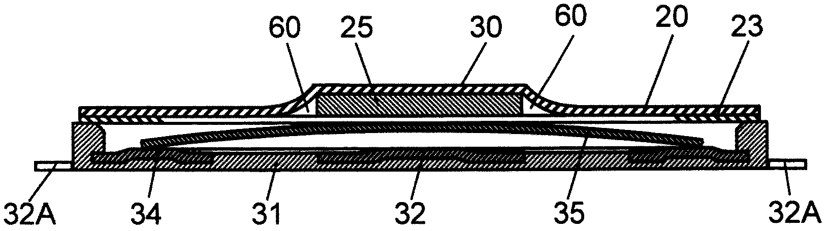
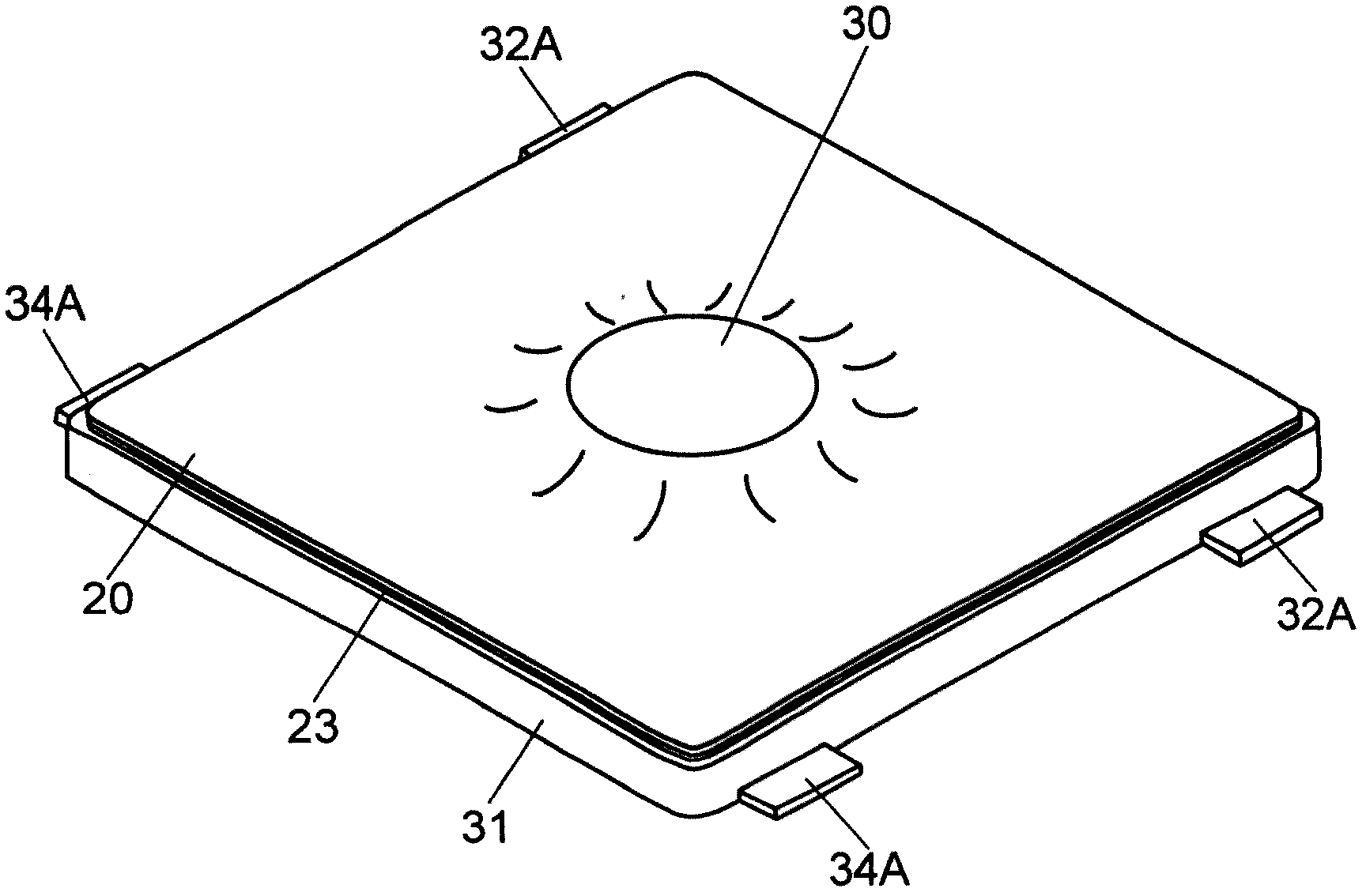
[0018] figure 1 It is a sectional view of the key switch according to Embodiment 1 of the present invention. figure 2 It is an external perspective view of the push switch in the embodiment of the present invention.

[0019] The key switch includes: a housing 31 having a recess; a central contact 32 (first fixed contact) disposed in the recess; and an outer contact 34 (second fixed contact) disposed in the recess. The key switch also includes: a dome-shaped movable contact 35 disposed in the recess, and the central part and the central contact 32 have intervals opposite to each other; a protective sheet 20 covering the recess; On the side, the protrusion member 25 fixed to the protective sheet 20 by welding.

[0020] The housing 31 has a concave portion opened above and is formed of resin in a rectangular shape. The center contact 32 and the outer contact 34 are fixed to the inner bottom surface of the concave portion of the case 31 by insert molding.

[0021] The centra...

Embodiment approach 2

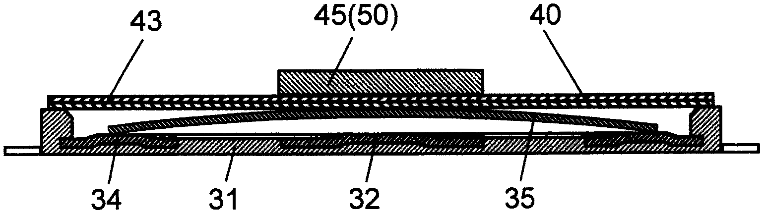
[0033] image 3 It is a sectional view of the key switch according to Embodiment 2 of the present invention. Figure 4 It is an external perspective view of the push switch according to Embodiment 2 of the present invention.

[0034]The key switch according to Embodiment 2 differs from the key switch according to Embodiment 1 in the arrangement position of the projection member 45 . That is, the protrusion member 45 is fixed to the surface of the protection sheet 40 opposite to the surface facing the movable contact 35 of the protection sheet 40 by welding. In addition, the same code|symbol is attached|subjected to the same component as Embodiment 1, and detailed description is abbreviate|omitted.

[0035] A protection sheet 40 covering a concave portion of the case 31 is attached to an upper end of the case 31 housing the movable contact 35 . The protrusion member 45 is welded to the upper surface side of the protective sheet 40, and the protrusion member 45 is exposed. T...


PUM


Abstract

A push switch includes a case having a recess portion, a first fixed contact placed in the recess portion, and a second fixed contact placed in the recess portion. Furthermore, the push switch includes a dome-shaped movable contact placed in the recess portion and having a center portion facing the first fixed contact with a space therebetween, a protective sheet for covering the recess portion, and a protrusion member fixed to the protective sheet by welding at a convex side of the center portion of the movable contact. The first fixed contact and the second fixed contact are provided at positions that are brought into contact with the movable contact when the movable contact is elastically reversed.

Description

technical field [0001] The present invention relates to a key switch used in an input operation unit of various electronic devices and a manufacturing method thereof. Background technique [0002] In recent years, push switches having protrusions at operating positions have been mounted on various electronic devices. Figure 5 It is a cross-sectional view of a conventional push switch. Figure 6 It is a perspective view of the appearance of a conventional key switch. [0003] The case 1 is formed of a resin having a concave portion opened above. The center contact 2 and the outer contacts 4 are fixed to the inner bottom surface of the concave portion of the housing 1 . The central contact 2 is connected to a first terminal 2A derived from the housing 1 , and the outer contact 4 is connected to a second terminal 4A derived from the housing 1 . A movable contact 5 made of a thin metal plate having a circular dome shape and a central portion protruding upward is housed in th...

Claims


Application Information

Patent Timeline
Patent Type & Authority Applications(China)
IPC IPC(8): H01H13/10H01H13/12H01H11/00
CPCH01H2229/036H01H2227/016H01H13/88H01H2011/0087H01H2229/02H01H2227/026H01H13/705H01H2221/05H01H2205/016Y10T29/49105
Inventor 中冈祐辅竹内正次
Owner PANASONIC CORP
Why Eureka
Try Eureka