Objective lens for endoscopes

a technology of endoscopes and lenses, applied in the field of objective lenses, can solve the problems of increasing the angle of view, and achieve the effect of compact design and favorable image quality

Active Publication Date: 2009-06-25
OLYMPUS CORP
View PDF7 Cites 69 Cited by
  • Summary
  • Abstract
  • Description
  • Claims
  • Application Information

AI Technical Summary

Benefits of technology

[0017]According to the present invention, the objective lens for endoscopes is obtained in which variation in the angle of view is kept to a minimum and at the same time, aberration can be completely corrected to obtain favorable image quality and the compact design can be attained. The objective lens for endoscopes is useful in the fields of medicine and industry in which it is needed that the endoscope is used to observe the hole of fine diameter such as a tubule in the body of the patient.

Problems solved by technology

However, when the first surface is configured to be flat, there is the problem that variation of the angle of view is increased.

Method used


Image

  • Objective lens for endoscopes
  • Objective lens for endoscopes
  • Objective lens for endoscopes

Examples


embodiment 1

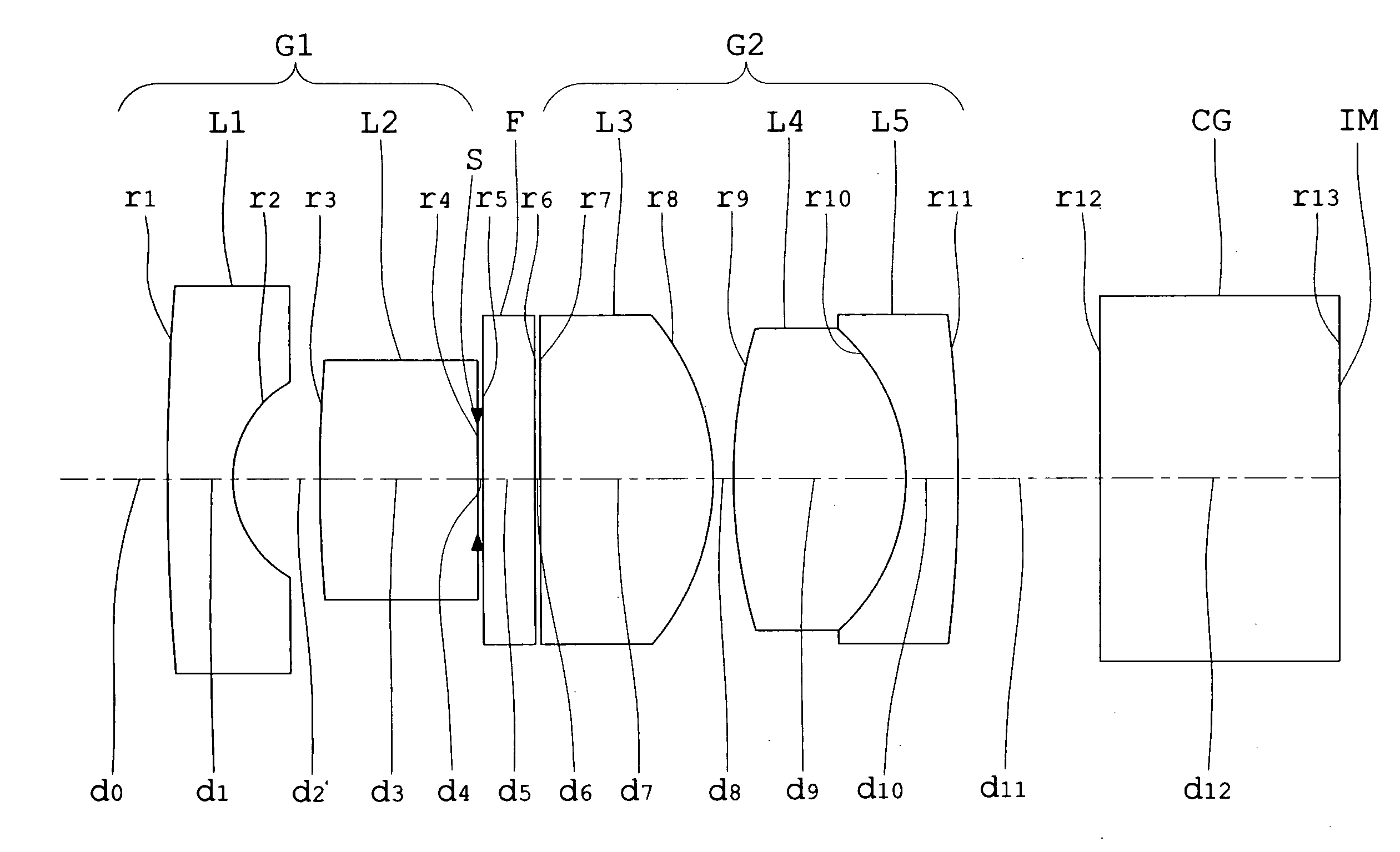
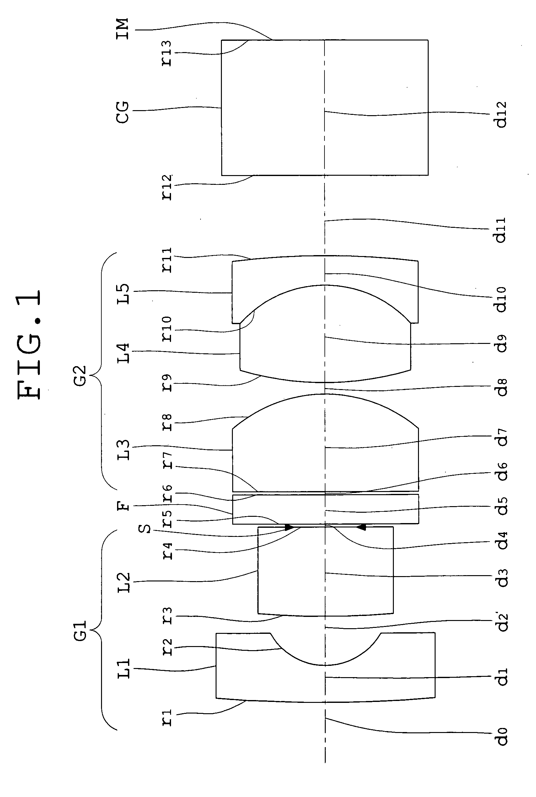
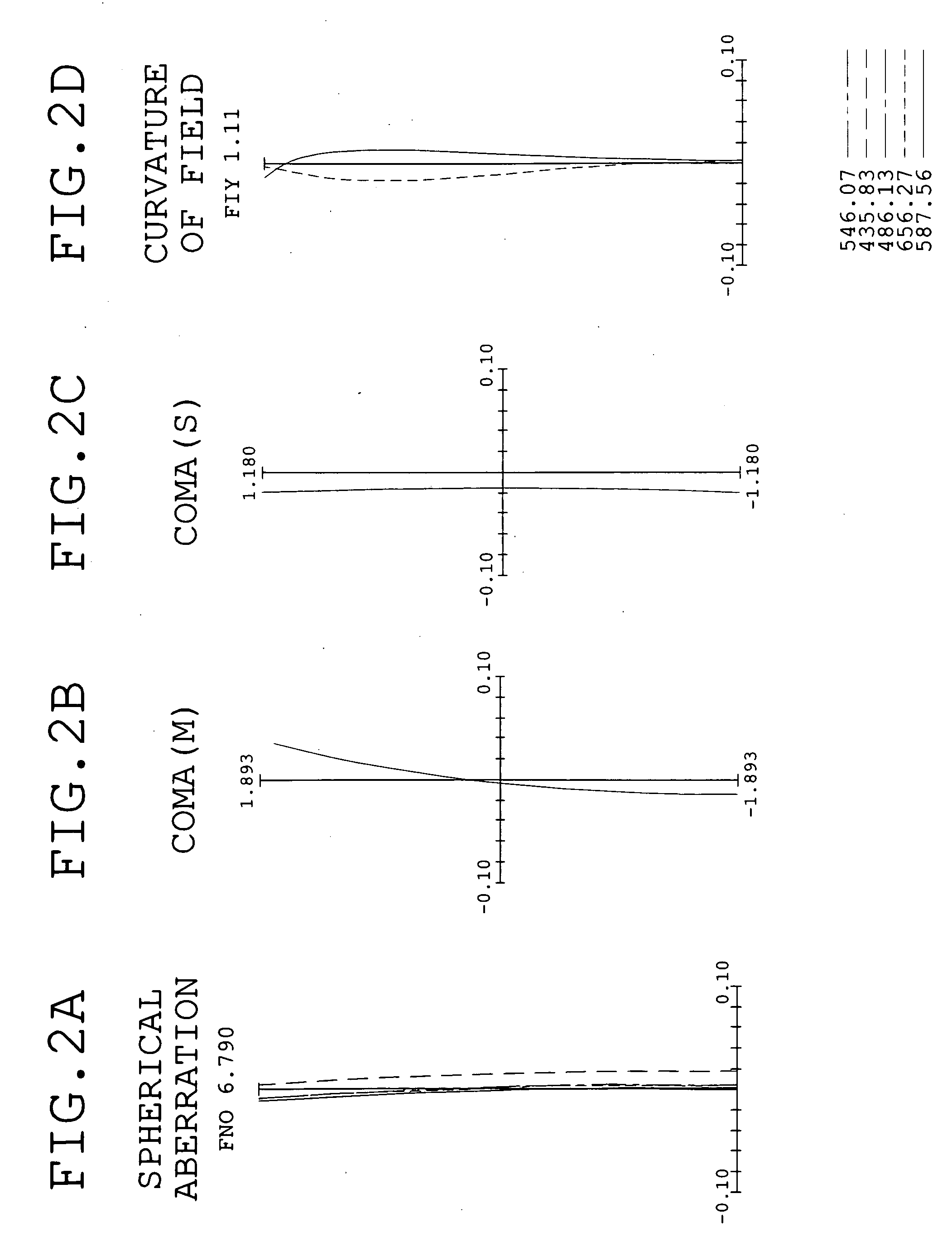
[0071]FIG. 1 is a sectional view showing an optical arrangement, developed along the optical axis, of the objective lens for endoscopes of Embodiment 1 according to the present invention. FIGS. 2A, 2B, 2C, and 2D are graphs showing spherical aberration, coma (meridional rays), coma (sagittal rays), and curvature of field, respectively, in the optical system of Embodiment 1.

[0072]The objective lens for endoscopes of Embodiment 1 has a front lens unit G1 and a rear lens unit G2 with an aperture stop S and a filter F between them. In FIG. 1, reference symbol CG denotes a cover glass and IM denotes an image plane. Here, the filter F is an infrared cutoff filter. In the objective lens for endoscopes of Embodiment 1, a part of a third lens element L3 whose center thickness is relatively large is replaced with the infrared cutoff filter and the replaced infrared cutoff filter is introduced into an objective optical system in such a way that it is interposed between the third lens element L...

embodiment 2

[0076]FIG. 3 is a sectional view showing an optical arrangement, developed along the optical axis, of the objective lens for endoscopes of Embodiment 2 according to the present invention. FIGS. 4A, 4B, 4C, and 4D are graphs showing spherical aberration, coma (meridional rays), coma (sagittal rays), and curvature of field, respectively, in the optical system of Embodiment 2.

[0077]The objective lens for endoscopes of Embodiment 2 has the front lens unit G1 and the rear lens unit G2 with the aperture stop S between them. In FIG. 3, reference symbol F denotes the filter, CG denotes the cover glass, and IM denotes the image plane. A fundamental arrangement of lens elements in each of the front lens unit G1 and the rear lens unit G2 is almost the same as in Embodiment 1. Also, Embodiment 2 is such that the infrared cutoff filter F is placed behind the rear lens unit G2. As described in Embodiment 1, the filter may be located at any position between the front lens unit G1 and the rear lens...

embodiment 3

[0079]FIG. 5 is a sectional view showing an optical arrangement, developed along the optical axis, of the objective lens for endoscopes of Embodiment 3 according to the present invention. FIGS. 6A, 6B, 6C, and 6D are graphs showing spherical aberration, coma (meridional rays), coma (sagittal rays), and curvature of field, respectively, in the optical system of Embodiment 3.

[0080]The objective lens for endoscopes of Embodiment 3 has the front lens unit G1 and the rear lens unit G2 with the aperture stop S between them. In FIG. 5, reference symbol CG denotes the cover glass and IM denotes the image plane.

[0081]A fundamental arrangement of lens elements in each of the front lens unit G1 and the rear lens unit G2 is almost the same as in Embodiment 1.

[0082]Subsequently, numerical data of optical members constituting the objective lens for endoscopes of Embodiment 3 are shown below.

Numerical Embodiment 3Unit: mmSurface dataFaceRefractiveAbbe'sFace numberRadius of curvaturespacingindexnum...


PUM


Abstract

An objective lens for endoscopes has a front lens unit and a rear lens unit with an aperture stop between them. The front lens unit includes a first lens element with negative refracting power of a meniscus shape, with a convex surface facing the object side and a second lens element with positive refracting power, and the rear lens unit includes a third lens element with positive refracting power, with a surface of the minor radius of curvature facing the image side and a cemented lens component of a fourth lens element with positive refracting power and a fifth lens element with negative refracting power. The objective lens satisfies the following conditions:
−2<SF<−0.9
0.94<D/(f×sin θ)<1.7
0.86<(D1+D2−f1)/(2×f3)<1.13
where SF is the shape factor of the first lens element and is a value expressed by SF=(R2+R1)/(R2−R1) when the radius of curvature of the object-side surface is denoted by R1 and the radius of curvature of the image-side surface is denoted by R2; D is a distance (an equivalent-air medium length) from the vertex of the image-side surface of the first lens element to the aperture stop; f is the combined focal length of the entire system; θ is a half angle of view; D1 is an actually measured distance from the vertex of the object-side surface of the first lens element to the aperture stop; D2 is a distance (an equivalent-air medium length) from the aperture stop to the image-side surface of the third lens element; f1 is the focal length of the first lens element; and f3 is the focal length of the third lens element.

Description

[0001]This application claims benefits of Japanese Patent Application No. 2007-330440 filed in Japan on Dec. 21, 2007, the contents of which are incorporated herein by reference.BACKGROUND OF THE INVENTION[0002]1. Field of the Invention[0003]This invention relates to an objective lens used in an endoscope.[0004]2. Description of Related Art[0005]Endoscopes have been used for observations of parts in which it is difficult to make external observations, like treatments and / or diagnoses of interiors of bodies of patients in a conventional field of medicine. Recently, a sleek design of the endoscope, represented by a nasal endoscope, has been needed and even for the objective lens used in the endoscope, downsizing of its outside diameter has been desired.[0006]Since a conventional objective lens used in the endoscope has a very large angle of view, a retrofocus-type lens system in which a plano-concave lens element is generally used at the most object-side position of the objective lens...

Claims


Application Information

Patent Timeline
Patent Type & Authority Applications(United States)
IPC IPC(8): G02B13/18G02B11/04
CPCG02B23/2407G02B13/04
Inventor SASAMOTO, TSUTOMU
Owner OLYMPUS CORP
Why Eureka
Try Eureka