
Mounting bracket for electronic device having dimensional inserts

a technology of mounting brackets and electronic devices, applied in the field of brackets and inserts, can solve the problems of mounting brackets, mounting poles, mounting brackets or both affecting the stability of the device, etc., and increasing the cos

Inactive Publication Date: 2007-02-27
INNOVATIVE OFFICE PROD LLC
View PDF12 Cites 68 Cited by
  • Summary
  • Abstract
  • Description
  • Claims
  • Application Information

AI Technical Summary

Benefits of technology

[0028]Another aspect of the present invention includes a kit for use in mounting a mountable d

Problems solved by technology

This direct contact between the mounting bracket and mounting pole often leads to scratching, stripping or deformation to either the mounting pole, mounting bracket or both.
In addition, mounting brackets may also cause the gouging of a channel or deep scratch on the surface of the mounting pole.
These channels or deep scratches further loosen the mounting bracket and ultimately may cause the bracket and / or mounting pole to need replacement, which also increases costs.
Additionally, over time, an originally tight mounting bracket-mounting pole interconnection may loosen, thereby allowing the mountable device to move from its preferred position.
While mounting brackets are typically made for use with a range of mounting pole sizes, these sizes are necessarily limited to a range of mounting pole sizes due to the size of the mounting bracket itself.
It is thus expensive to change the size of a mounting bracket.

Method used


Image

  • Mounting bracket for electronic device having dimensional inserts
  • Mounting bracket for electronic device having dimensional inserts
  • Mounting bracket for electronic device having dimensional inserts

Examples


Embodiment Construction

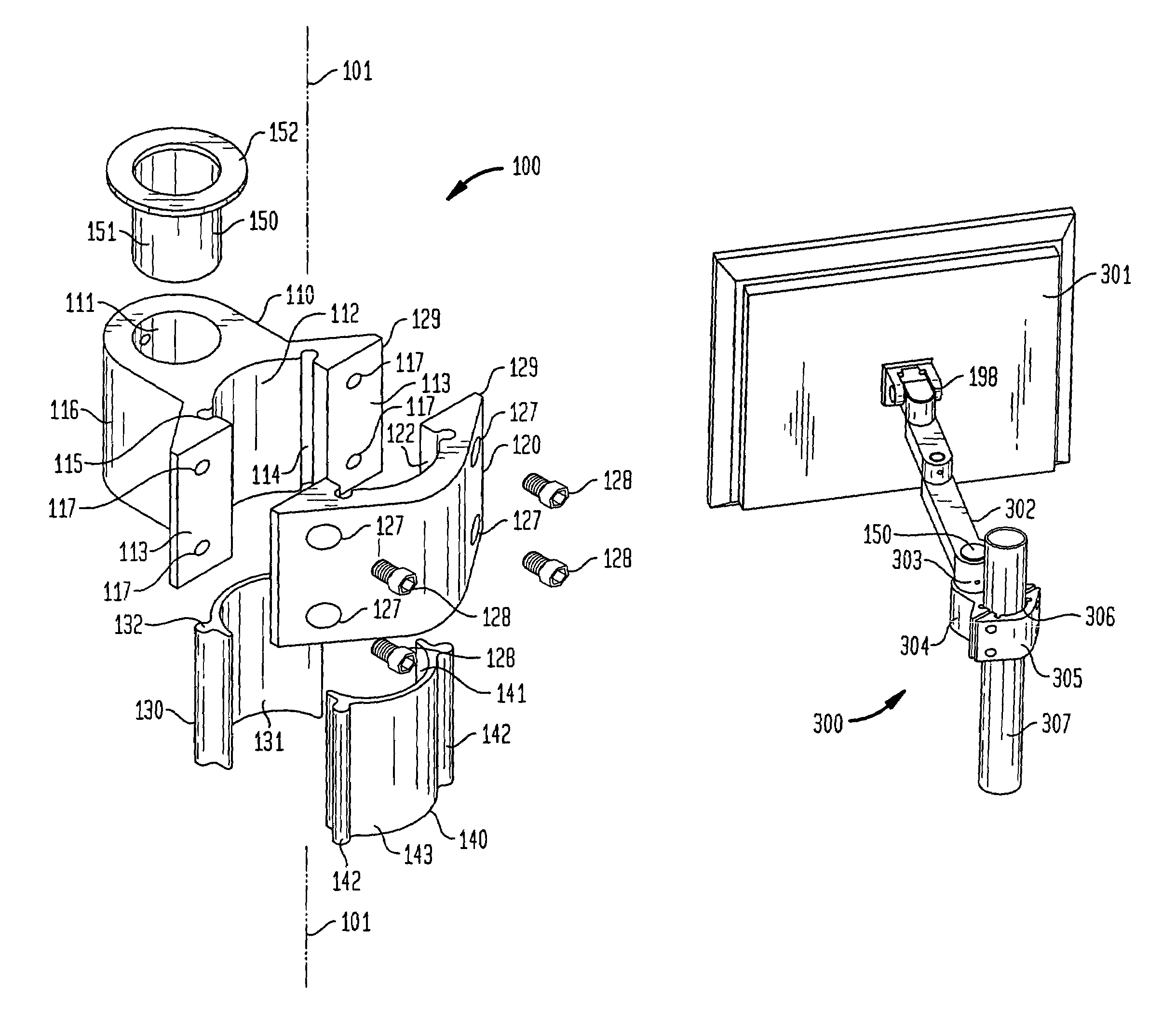
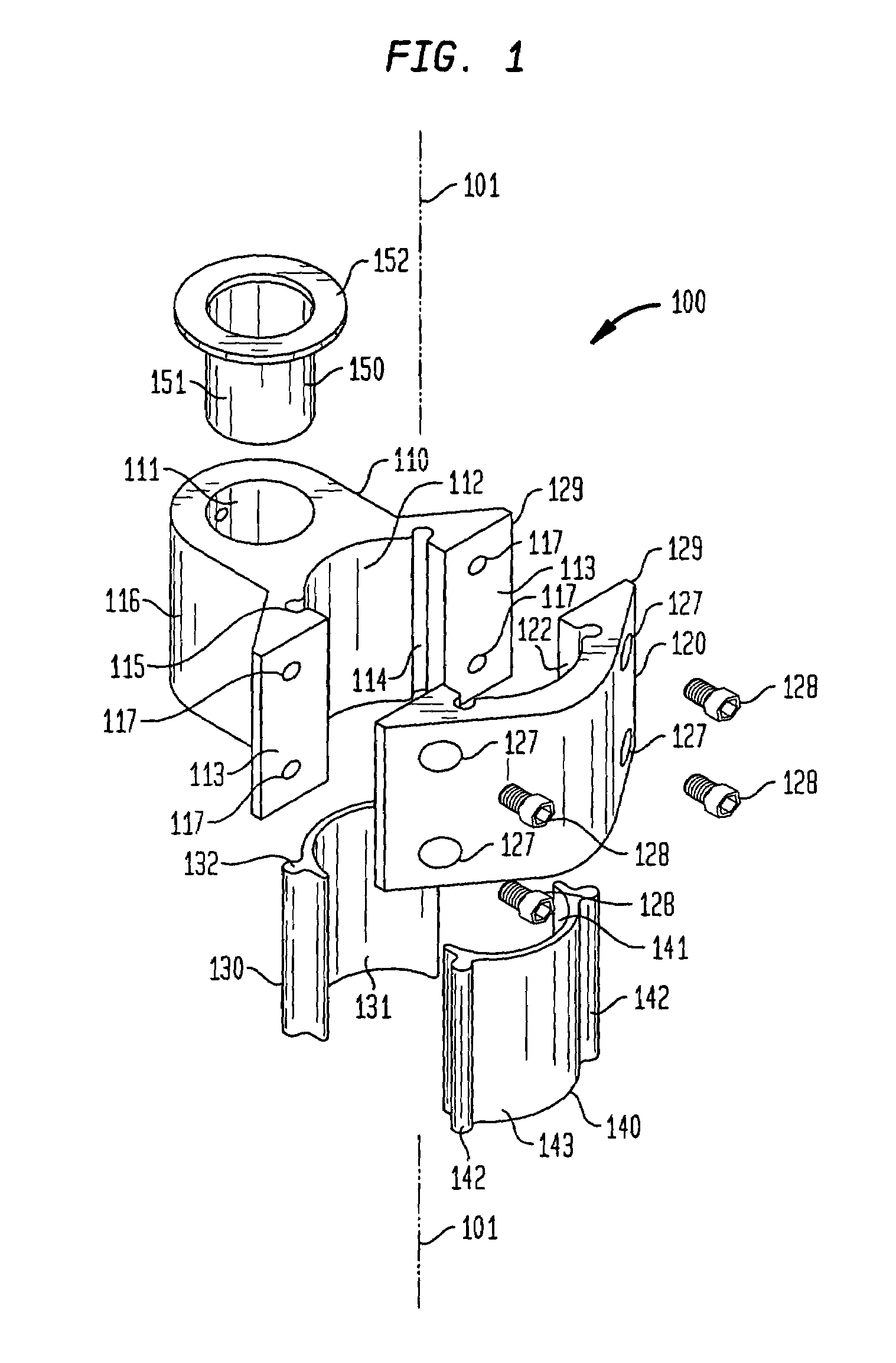
[0042]The present invention advantageously provides a mounting bracket and insert that together allow the secure coupling of a mountable device assembly to a mounting pole.

[0043]It also advantageously allows for the bracket to tightly grip the mounting pole without damage resulting to either the bracket or to the mounting pole. Instead, a generally less expensive insert is used between the bracket and the mounting pole to moderate the potential damage to the mounting pole or bracket, and to prevent slippage of either.

[0044]Additionally, due to the tight grip the bracket and insert can have on the mounting pole, the mountable device so mounted is securely in a fixed position and less likely to move due to slippage at the bracket / insert-mounting pole coupling.

[0045]The present invention also advantageously provides for a single bracket size to accommodate mounting poles of different diameter and geometry. When a bracket is overly large for the mounting pole in use, instead of changing...


PUM


Abstract

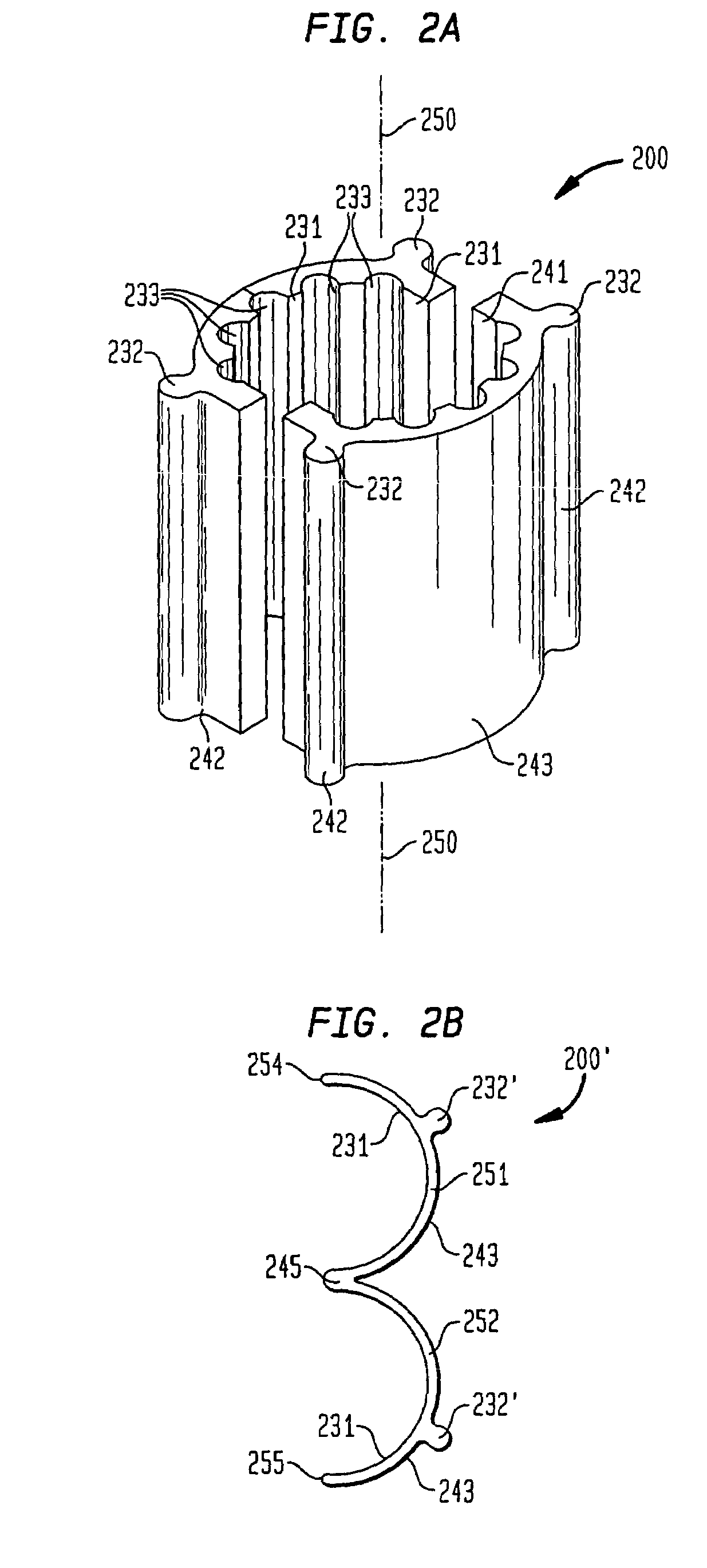
A mounting bracket and insert for use in mounting mountable devices to a mounting pole including a first section and a second section, each of said first and second sections having a concave surface, each concave surface having at least a one longitudinally extended groove, the first and second sections being joinable to one another, with such joining forming a cylindrical area between the first and second sections, said cylindrical area formed by said concave surfaces, and at least a pair of inserts, each insert having a convex surface sized to fit within the concave surface of one of the two sections, the convex surface of each insert having at least one protrusion aligned along the longitudinal axis of the insert and shaped to fit into at least one groove of the concave surfaces of the sections is described.

Description

BACKGROUND OF THE INVENTION[0001]The present invention relates to brackets and inserts for coupling a mountable device to a mounting pole.[0002]Mounting brackets are typically used to affix mountable devices to mounting poles. Conventionally, when a device, such as a video display, computer terminal, video camera, scoreboard, etc., must be visible from a distance or from a certain vantage point, it is mounted to a mounting pole. This allows the device to use less floor or desk space, and also allows the device to be raised to a higher position, thus allowing for greater visibility.[0003]Usually, coupling a mountable device to a mounting pole requires the use of a mounting bracket. The mounting bracket conventionally attaches to the mounting pole at one end and to the mountable device at the opposite end. See U.S. Pat. No. 6,499,704.[0004]While conventional mounting brackets function as designed, in order to get and maintain a tight grip on the mounting pole, a conventional mounting ...

Claims


Application Information

Patent Timeline
IPC IPC(8): A47F5/00
CPCF16M13/02F16M11/10F16M11/24F16M13/022F16M11/2014Y10T403/451
Inventor ODDSEN, JR., ODD N.WILLIAMS, JR., HOWARD M.
Owner INNOVATIVE OFFICE PROD LLC
Learn More