Imaging lens and camera system including the same lens

a technology of imaging lens and camera system, applied in the field of imaging lens, can solve the problems of large field curvature, large distortion, deterioration of image quality in a peripheral portion thereof, etc., and achieve the effect of suppressing the deterioration of lens performance attributed to thermal expansion and good weathering resistan

Active Publication Date: 2009-12-29
TIANJIN OFILM OPTO ELECTRONICS CO LTD
View PDF7 Cites 73 Cited by
  • Summary
  • Abstract
  • Description
  • Claims
  • Application Information

AI Technical Summary

Benefits of technology

[0007]The invention has been made in view of the problems inherent in the related art, and an object thereof is to provide an imaging lens which can maintain a good optical performance and which is small in size, light in weight and low in cost and a camera which includes the imaging lens.
[0009]In addition, according to the invention, the second lens is a double-convex lens, whereby field curvature is corrected properly. Additionally, the fourth lens is a double-convex lens, whereby chromatic aberration is corrected properly. Note that by making the third lens be made up of a double-convex lens, the field curvature can be corrected further properly.
[0014]In addition, according to the invention, a linear expansion coefficient of a material for the first lens to the fifth lens is 12×10−6 [1 / K] or less, thereby making it possible to obtain an imaging lens which is suitable for an onboard camera which is used under an environment such as occurring in the passenger compartment of a vehicle during summer time in which the temperature becomes high. Note that by attaining preferably a linear expansion coefficient of 11×10−6 [1 / K] and more preferably a linear expansion coefficient of 10.5×10⁻⁶ [1 / K], the deterioration in performance of the lens attributed to thermal expansion can be suppressed.
[0015]According to the invention, there can be provided a camera system including an imaging lens as set forth and a solid state imaging device for converting an optical image picked up by the imaging lens into an electric signal, which is suitable for onboard cameras or the like for which good weathering resistance and thermal expansion resistance are required.

Problems solved by technology

With the imaging lens described in JP-A-1-265216, there is provided a drawback that the field curvature is large.
With the imaging lens described in JP-A-2004-145256, there is provided a drawback that the distortion is large, and hence, images picked up by the relevant lens have to be processed to be displayed on a monitor and image quality in a peripheral portion thereof is deteriorated.
The imaging lenses described in JP-A-2004-61763 and JP-A-2004-354888 are lenses developed for endoscopes, and their f numbers which are 3.5 or larger present a drawback that the lenses with those f numbers too dark to be used as onboard cameras and monitor cameras.

Method used


Image

  • Imaging lens and camera system including the same lens
  • Imaging lens and camera system including the same lens
  • Imaging lens and camera system including the same lens

Examples


embodiment 1

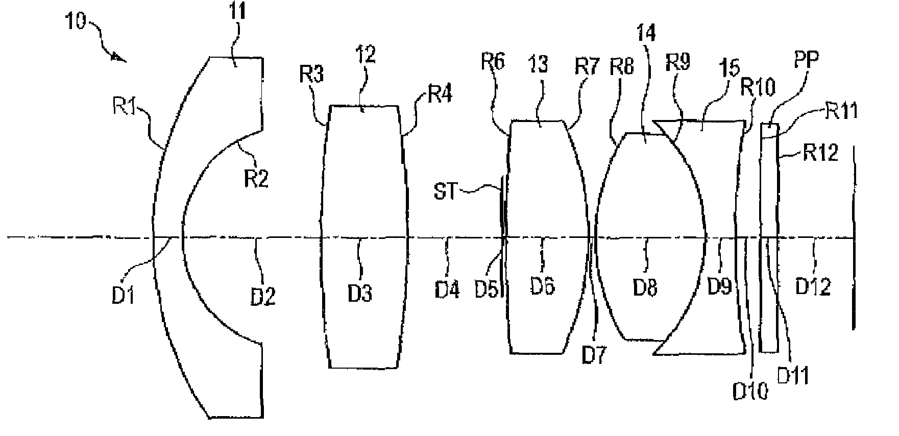
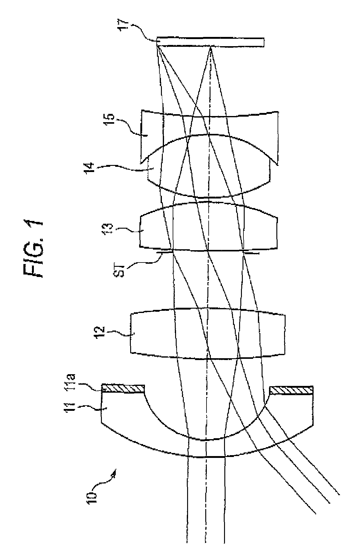
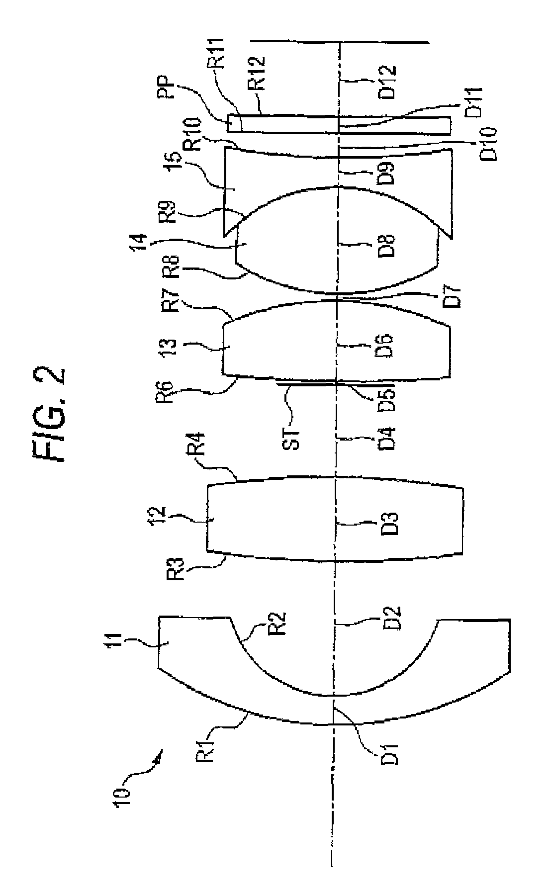
[0043]In FIGS. 1 and 2, an imaging lens 10 includes, in order from an object side, a first lens 11, a second lens 12, a third lens 13, a fourth lens 14 and a fifth lens 15. The first to fifth lenses are all glass spherical lenses. The first lens 11 has a negative meniscus shape with a convex surface directed to an object side and a concave surface directed to an image side thereof. A light cut-off film 11a is provided on an area which is located radially outwards of the image side concave surface of the first lens 11. The light cut-off film prevents the entrance of light from the outside of an effective aperture so as to prevent the occurrence of a ghost image on an image plane. In addition, although the light cut-off film 11a is an opaque paint layer which is provided on the outside of the effective aperture, an opaque plate material may be provided on A rear side of the first lens 11. In addition, the position where the light cut-off film 11a is provided is not limited to the rear...

embodiment 2

[0051]In FIG. 4, an imaging lens 20 includes, in order from an object side, a first lens 21, a second lens 22, a third lens 23, a fourth lens 24 and a fifth lens 25. The first lens 21 has a negative meniscus shape with a convex surface directed to an object side and a concave surface directed to an image side thereof. The second lens 22 has a double-convex shape with convex surfaces directed to both of an object side and an image side thereof, respectively, and an absolute value of a radius of curvature of the convex surface on the image side is smaller than that on the object side. An aperture stop ST is provided between the second lens 22 and the third lens 23. The third lens 23 has a double-convex shape with convex surfaces directed to both of an object side and an image side thereof, respectively, and an absolute value of a radius of curvature of the convex surface on the image side is smaller than that on the object side. The fourth lens 24 has a double-convex shape with convex...

embodiment 3

[0055]In FIG. 6, an imaging lens 30 includes, in order from an object side, a first lens 31 to a fifth lens 35. The first lens 31 has a negative meniscus shape with a convex surface directed to an object side and a concave surface directed to an image side thereof. The second lens 32 has a double-convex shape with convex surfaces directed to both of an object side and an image side thereof, respectively, and an absolute value of a radius of curvature of the convex surface on the image side is smaller than that on the object side. An aperture stop ST is provided between the second lens 32 and the third lens 33. The third lens 33 has a double-convex shape with convex surfaces directed to both of an object side and an image side thereof, respectively, and an absolute value of a radius of curvature of the convex surface on the image side is smaller than that on the object side. The fourth lens 34 has a double-convex shape with convex surfaces directed to both of an object side and an im...


PUM


Abstract

An imaging lens comprises, in order from an object side: a first lens having a negative refractive power with a concave surface directed to an image side thereof; a second lens having a positive refractive power with a convex surface directed to an image side thereof and having an absolute value of a radius of curvature on the image side is equal to or smaller than that on an object side thereof; an aperture stop; a third lens which is a planoconvex lens having a plane on an object side thereof or a double-convex lens having on an object side thereof a surface of which an absolute value of a radius of curvature is larger than that on an image side thereof; and a compound lens of a fourth lens and a fifth lens, the compound lens having a positive composite power.

Description

BACKGROUND OF THE INVENTION[0001]1. Field of the Invention[0002]The present invention relates to an imaging lens for forming an optical image on a solid state imaging device which is suitable for use for an onboard camera, a monitor camera, a mobile terminal camera and the like and a camera system which utilizes the imaging lens.[0003]2. Description of the Related Art[0004]Onboard cameras are known which pick up images of surroundings of a motor vehicle on which the cameras are installed to show the driver conditions surrounding the vehicle via images on a monitor screen (for example, refer to JP-A-2006-168683). These onboard cameras include, for example, an outside camera which is provided on an outside of the vehicle for assisting the driver to drive the vehicle by picking up images of surroundings which lie within a blind range to the driver and an inside camera which is designed to pick up images of conditions resulting when the vehicle is involved in a traffic accident in the s...

Claims


Application Information

Patent Timeline
Patent Type & Authority Patents(United States)
IPC IPC(8): G02B9/60G02B9/34
CPCG02B13/04G02B9/34
Inventor ASAMI, TARO
Owner TIANJIN OFILM OPTO ELECTRONICS CO LTD
Why Eureka
Try Eureka