Structure support apparatus and structure installation method

a technology of structure support and installation method, which is applied in the direction of building repair, application, lighting and heating apparatus, etc., can solve the problems of increasing the number of parts, requiring time and effort to perform this processing, and poor durability

Inactive Publication Date: 2008-03-06
SHARP KK
View PDF19 Cites 67 Cited by
  • Summary
  • Abstract
  • Description
  • Claims
  • Application Information

AI Technical Summary

Benefits of technology

[0010] Having been conceived in light of the stated problems with the conventional art, it is an object of the present invention to provide a structure support apparatus capable of improved strength, and having excellent durability, a small number of parts, and an easy installation procedure, without significantly increasing the size.
[0019] The bowed plate and the dome-shaped convex portion are a single structure, which makes the installation thereof easy and increases the strength while at the same time suppressing an increase in size.
[0021] Furthermore, a reinforcement member is provided on the inner side of the dome-shaped convex portion, and the screw hole passes through the bowed plate and the reinforcement member. Through this reinforcement member, the strength of the dome-shaped convex portion can be improved, and deformation of the dome-shaped convex portion due to the force exerted by the screws can be prevented, while allowing the bowed plate to be pressed down strongly and anchored to the roof through the force exerted by the screws.
[0024] According to the installation method of the present invention, part of the bowed plate is inserted between roof material portions vertically overlapping in a stepped pattern on the roof. In this case, the space between the bowed plate and the roof facing up the slope of the roof is sheathed in roof material portions, preventing water from leaking in from this space. The bowed plate is arranged on a roof with the concave side of the bowed plate facing the surface of the roof. Screws are passed through the screw holes of the dome-shaped convex portion, screwed into the roof, and tightened down, thereby pressing the bowed plate down upon the roof and anchoring the bowed plate to the roof Therefore, the bowed plate is pushed strongly down upon the roof due to the force exerted by the screws, thus becoming flat in shape. At this time, the outer sides of the bowed plate tighten against the roof due to the elastic force of the bowed plate, making the area between the bowed plate and the roof water-resistant. Furthermore, the apex of the dome-shaped convex portion supports the structure; therefore, rainwater flows on the surface of the roof and the bowed plate and does not leak into the screw holes of the dome-shaped convex portion, which is in a higher position than these surfaces.

Problems solved by technology

However, according to the technology described in JP H8-93159A, the water-resistance processing involves filling the space around the support hardware with a sealant, and thus performing this processing requires time and effort.
Furthermore, the water resistance depends solely on the sealant used, and thus has poor durability.
When taken with screws, pins, and the like, the number of parts increases, which complicates the installation process.
Furthermore, when the size of the anchoring hardware is increased to improve its strength, the water-resistant covers that sheathe the anchoring hardware become extremely large and stand out, resulting in a visually unappealing sight after construction.

Method used


Image

  • Structure support apparatus and structure installation method
  • Structure support apparatus and structure installation method
  • Structure support apparatus and structure installation method

Examples


Embodiment Construction

[0038] An embodiment of the present invention shall be described hereinafter with reference to the drawings.

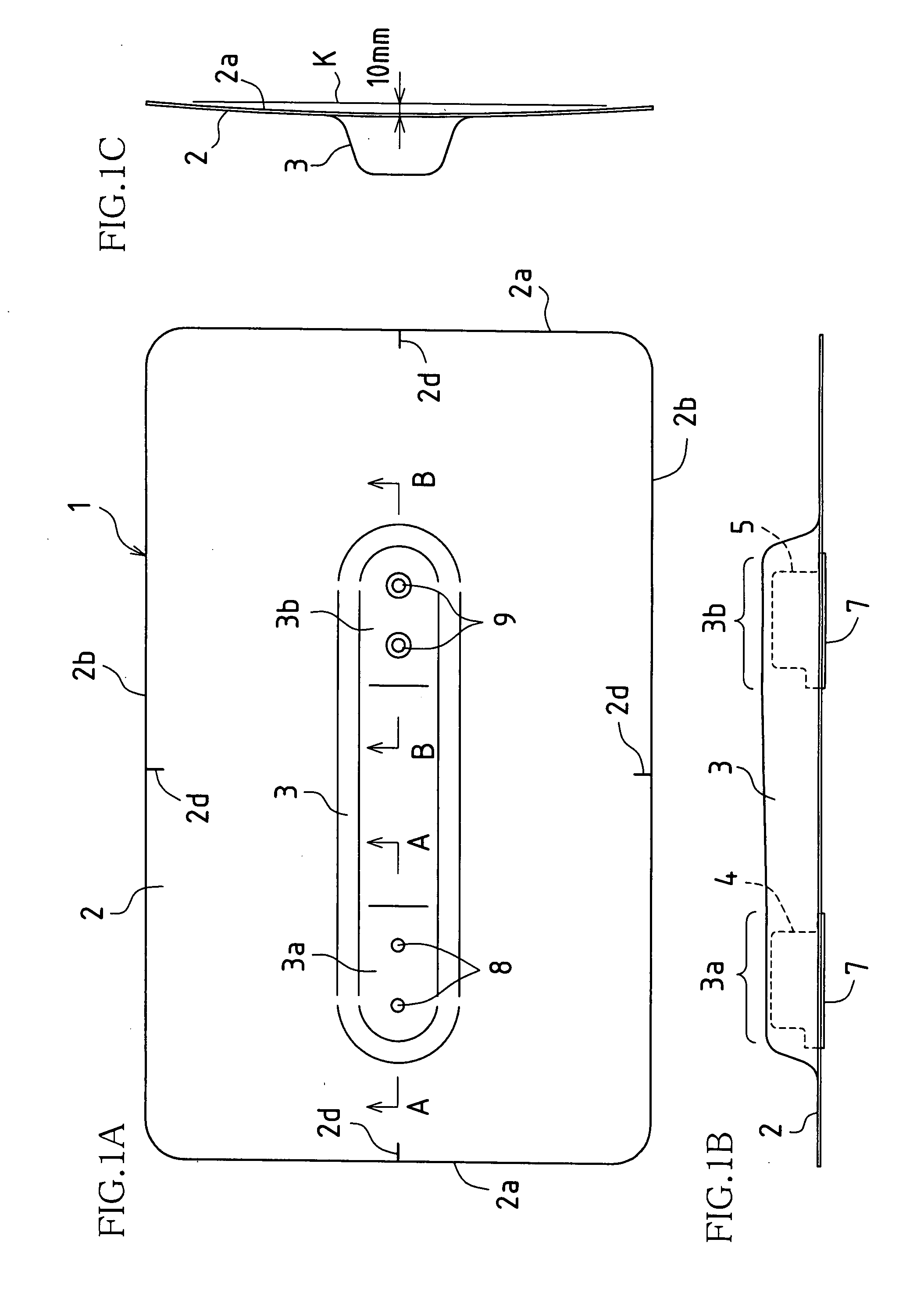
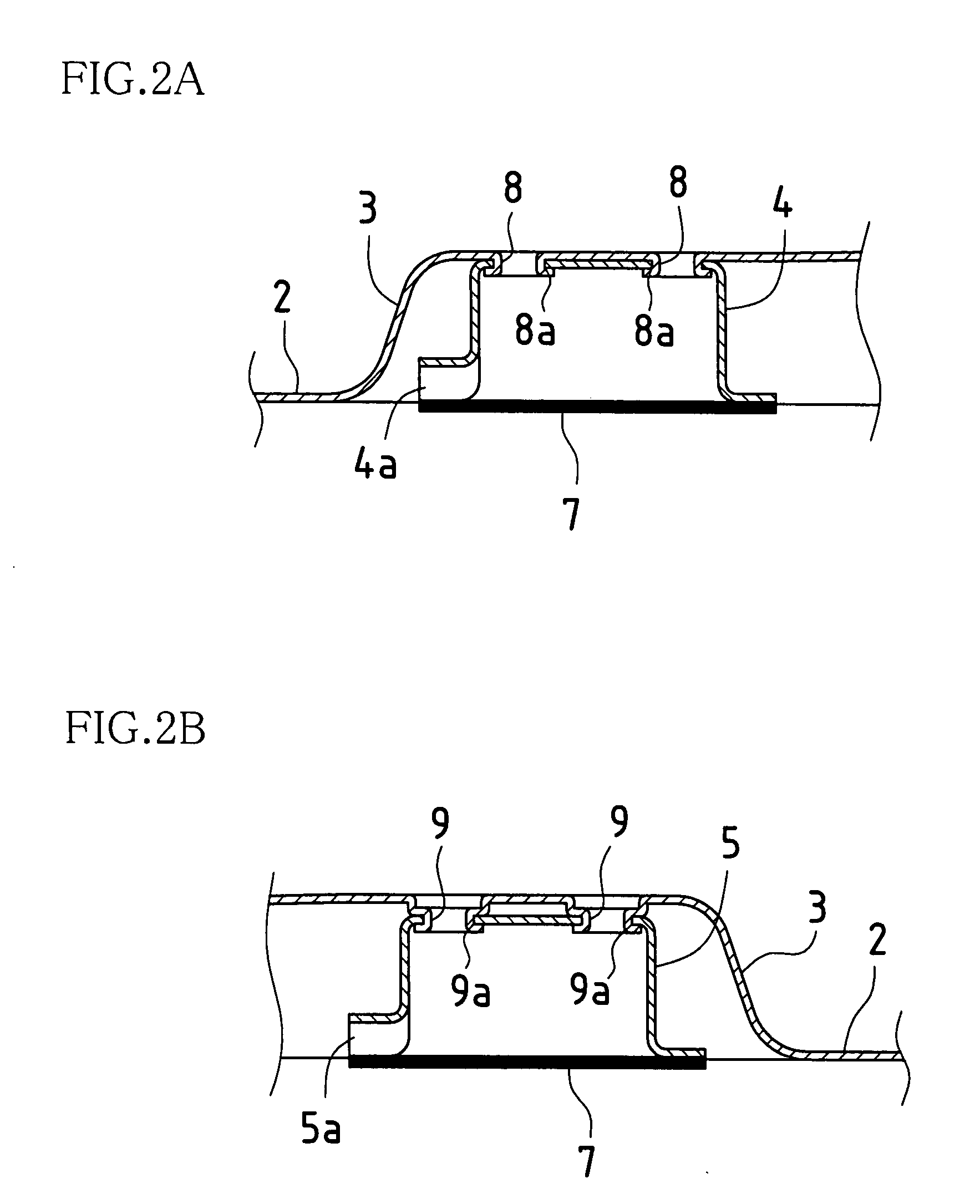
[0039]FIGS. 1A, 1B, and 1C are a plan view, a front view, and a side view of an embodiment of a structure support apparatus according to the present invention. Also, FIGS. 2A and 2B are cross-sections viewed along the A-A and B-B lines, respectively, indicated in FIG. 1A.

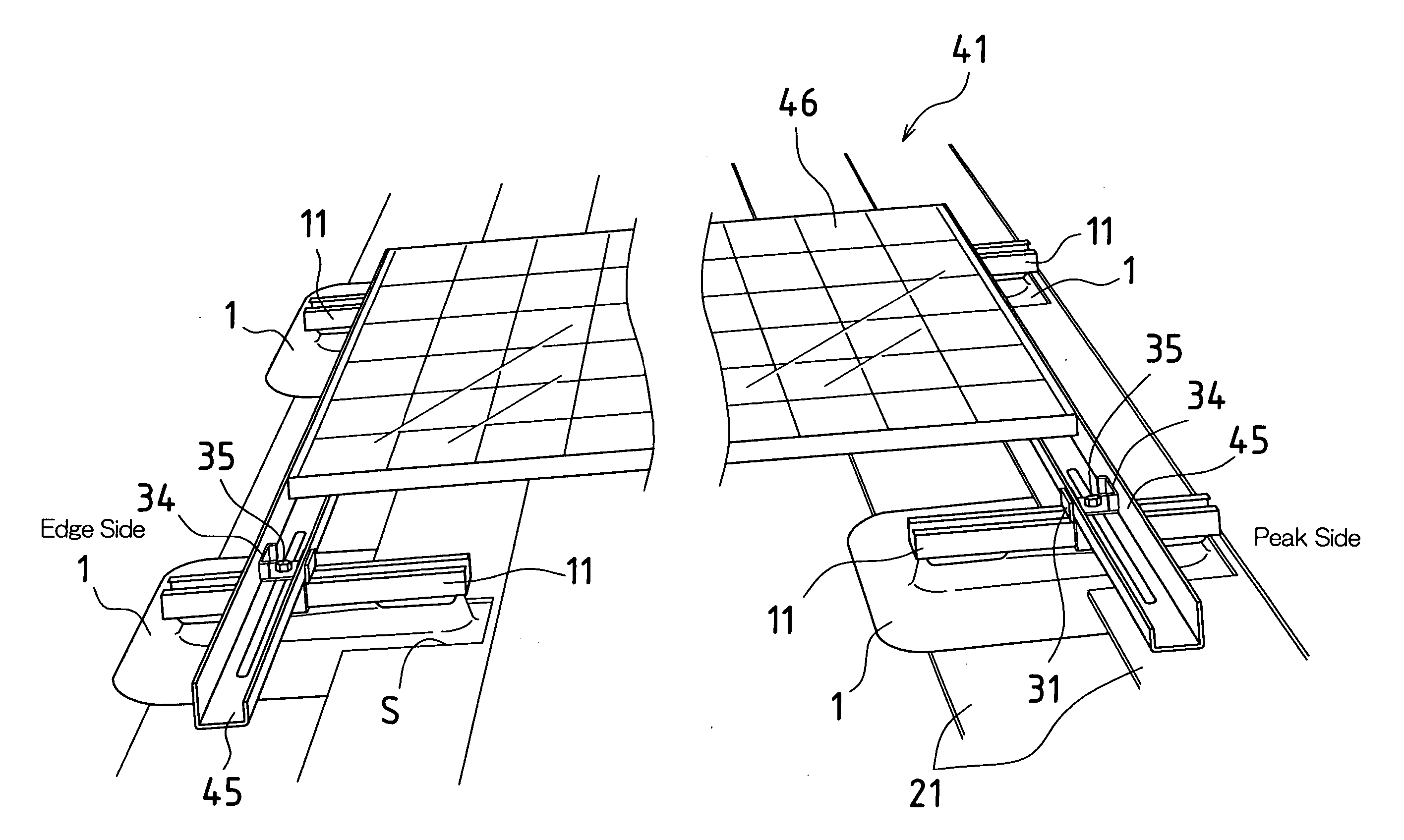
[0040] A structure support apparatus 1 of the present embodiment includes: a bowed plate 2, in which a rectangular metal plate has been caused to bow outward; a dome-shaped convex portion 3 protruding from the concave side to the convex side of the bowed plate 2 in a central area of the bowed plate 2; and two reinforcement members 4 and 5, disposed on the inner side of the dome-shaped convex portion 3. Furthermore, water-resistant butyl rubber sheets 7 are affixed to the bottom surfaces of the reinforcement members 4 and 5, and backing paper (not shown) is attached to the butyl rubber sheets 7.

[0041] Note t...


PUM


Abstract

According to an embodiment of the present invention, a structure support apparatus for anchoring and supporting a structure upon a roof comprises a bowed plate having a dome-shaped convex portion formed in the center of the bowed plate projecting from the concave side toward the convex side of the bowed plate. A screw hole is formed in the dome-shaped convex portion, penetrating the center of the bowed plate, and the structure is supported by the apex of the dome-shaped convex portion.

Description

CROSS REFERENCE TO RELATED APPLICATION [0001] This application claims priority under 35 U.S.C. §119(a) on Japanese Patent Application No. 2006-238089, filed Sep. 1, 2006, the content of which is hereby incorporated by reference in its entirety. BACKGROUND OF THE INVENTION [0002] 1. Field of the Invention [0003] The present invention relates to a structure support apparatus and structure installation method for supporting and anchoring a structure, such as a solar cell module used in a residential photovoltaic power generation system, to the roof or the like of a house. [0004] 2. Description of the Related Art [0005] A residential photovoltaic power generation system has been provided for energy conservation or effective use of solar energy. With this commonly-known system, a solar cell module is installed on the roof or the like of a house, and power generated by the solar cell module is supplied to the residence. Making use of this kind of system requires construction for installin...

Claims


Application Information

Patent Timeline
Patent Type & Authority Applications(United States)
IPC IPC(8): E04D13/18E04D13/00E04D5/14
CPCF24J2/4614F24J2/5205F24J2/5245F24J2/526H02S20/23Y02B10/12Y02B10/20Y02E10/47F24J2002/5294F24S25/61F24S2025/021F24S25/33F24S25/65F24S40/44Y02E10/50Y02B10/10
Inventor OHKOSHI, YASUSHITERUNUMA, MIHOARAMAKI, YOSHIHIRO
Owner SHARP KK
Why Eureka
Try Eureka