Image pickup lens, image pickup unit and cellphone terminal equipped therewith

a technology for image pickup and cellphone terminals, which is applied in the field of small-sized image pickup lenses to achieve the effect of small size and higher performan

Inactive Publication Date: 2005-04-26
KONICA MINOLTA INC
View PDF9 Cites 66 Cited by
  • Summary
  • Abstract
  • Description
  • Claims
  • Application Information

AI Technical Summary

Benefits of technology

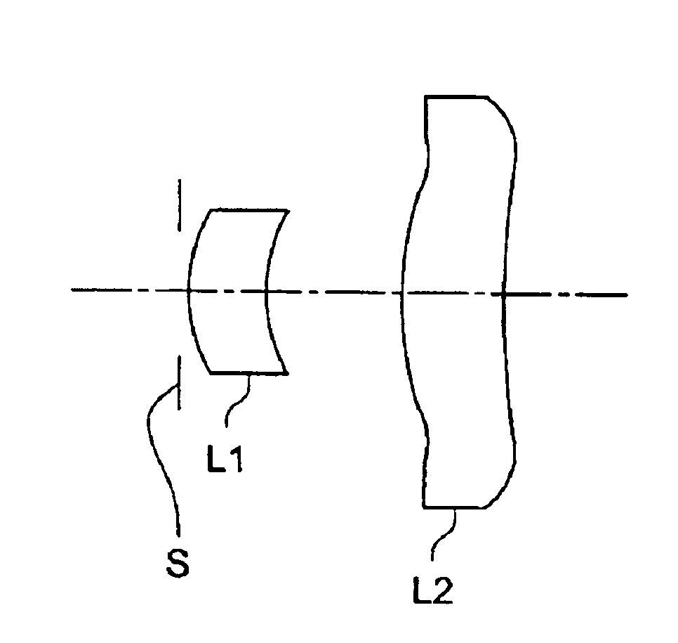
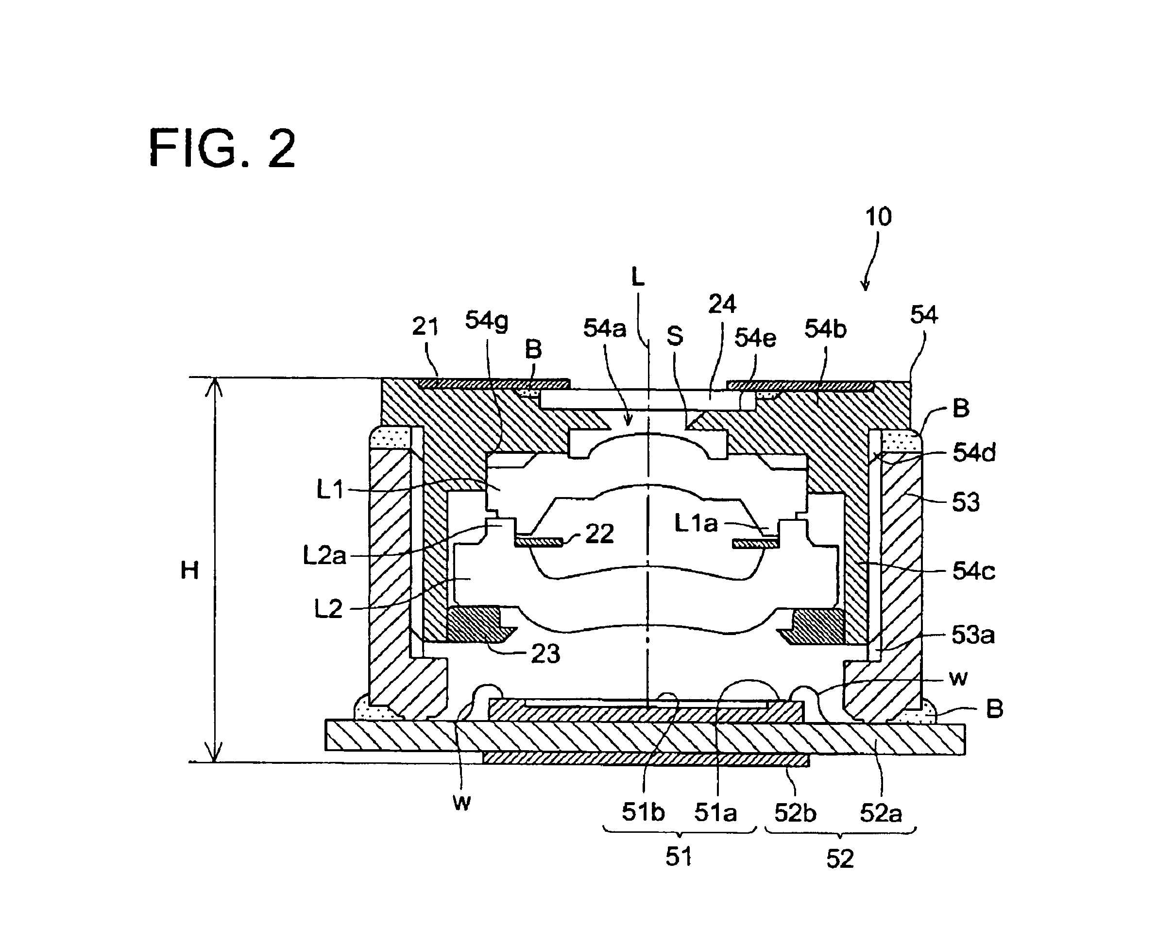
[0010]In the basic structure of the invention for obtaining a small-sized image pickup lens in which aberrations are corrected satisfactorily, an aperture stop is arranged to be closest to an object, and a meniscus-shaped positive first lens whose convex surface faces the object and a positive or negative second lens whose convex surface faces the object constitute the image pickup lens. By making the positive first lens to be in a meniscus shape where the convex surface faces an object, the principal point of the total system of the image pickup lens can be moved to be closer to an object, and thereby, the total length of the image pickup lens satisfying conditional expression (8) can be downsized. Further, by arranging an aperture stop to be closest to an object and by making an object-side surface of the second lens to be convex toward the object side, telecentric characteristics of an image-side light flux necessary for the image pickup lens that employs a charge coupled device can be secured easily.
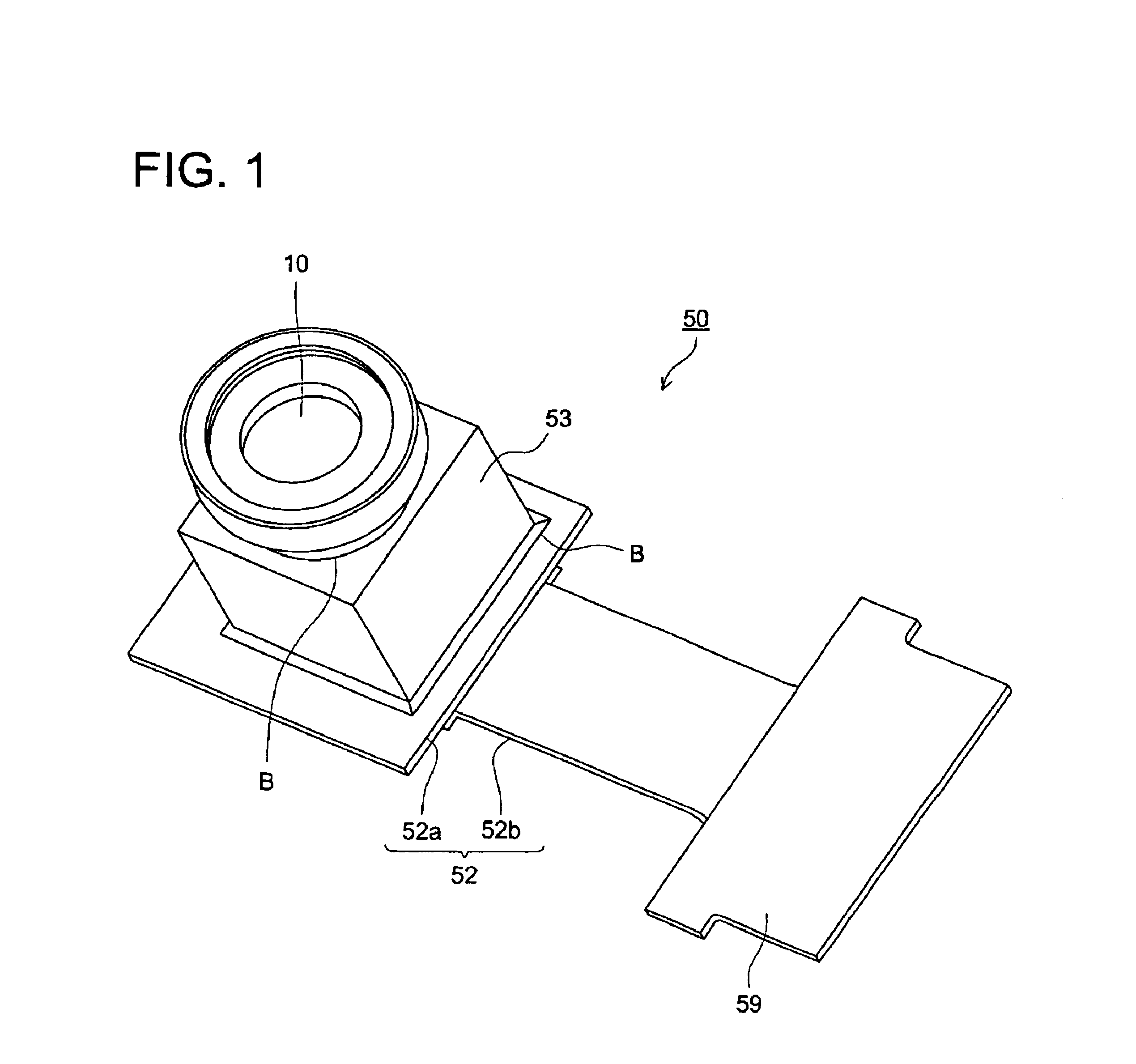
[0035]Structure (11): A cellphone terminal that is characterized to be equipped with the image pickup unit described in Structure (10). By using the image pickup unit described in the Structure, the cellphone terminal which is smaller in size and higher in performance can be obtained.

Problems solved by technology

There has been a problem in the lens of the type described in the patent official report mentioned above that an angle of view in the diagonal direction of a solid-state image sensor is as small as 52° to be slightly small as an image pickup lens to be used for a camera-fitted cellphone, although its f-number is as great as 2.0 and downsizing of the total lens length is achieved.

Method used


Image

  • Image pickup lens, image pickup unit and cellphone terminal equipped therewith
  • Image pickup lens, image pickup unit and cellphone terminal equipped therewith
  • Image pickup lens, image pickup unit and cellphone terminal equipped therewith

Examples


example

[0064]An example of an image pickup lens that can be used in the aforementioned embodiment will be shown below. Symbols to be used in each example are as follows.

[0065]f: Focal length of a total image pickup lens system

[0066]fB: Back focus

[0067]F: F-number

[0068]2Y: Length of a diagonal line on an image pickup surface of a solid-state image sensor (a length of a diagonal line on a practical rectangle pixel area of a solid-state image sensor)

[0069]2ω: Angle of view in the diagonal line direction on an image pickup surface of a solid-state image sensor

[0070]R: Radius of curvature

[0071]D: Axial distance between surfaces

[0072]Nd: Refractive index of lens material for d-line

[0073]vd: Abbe's number

[0074]A form of an aspheric surface in each example is shown by the following expression under the assumption that a vertex of the surface is the origin, X-axis is taken in the direction of an optical axis and h represents a height in the direction perpendicular to the optical axis; X=h2 / R41+1-(1...


PUM


Abstract

An image pickup lens that has therein, in the order named from an object side, an aperture stop, a meniscus-shaped first lens having positive refracting power whose convex surface faces an object and a second lens having positive or negative refracting power whose convex surface faces the object, wherein each of the first lens and the second lens has at least one aspheric surface and satisfies the following condition expression f1 / |f2|<1.0 wherein, f1 is a focal length of the first lens, f2 is a focal length of the second lens and f is a focal length of the entire system of the image pickup lens.

Description

BACKGROUND OF THE INVENTION[0001]The present invention relates to a small-sized image pickup lens employing, an image pickup unit and a cellphone terminal equipped with the small-sized image pickup lens and the image pickup unit, employing a solid-state image sensor such as a solid-state image sensor of a CCD type or a solid-state image sensor of a CMOS type.[0002]With high efficiency and downsizing of an image pickup unit employing a solid-state image sensor such as an image sensor of a CCD (Charge Coupled Device) type or an image sensor of a CMOS (Complementary Metal Oxide) type, a cellphone and a personal computer each being provided with the image pickup unit are spreading in recent years. In addition, a demand for further downsizing of the image pickup lens equipped on each of these image pickup units is increasing.[0003]A two-element lens capable of being improved to be of the higher efficiency compared with a single lens is generally fit for the image pickup lens to be used f...

Claims


Application Information

Patent Timeline
Patent Type & Authority Patents(United States)
IPC IPC(8): G02B13/18G02B9/06G02B9/10G02B9/00H04N5/225G02B13/00
CPCG02B9/06G02B9/10H04N5/2254G02B13/18H04N5/2253G02B13/003H04N23/54H04N23/55
Inventor YAMAGUCHI, SUSUMUSATO, MASAE
Owner KONICA MINOLTA INC
Why Eureka
Try Eureka