Patch antenna for directional diagram and frequency scanning

A patch antenna and frequency scanning technology, which is applied to antennas, antenna supports/installation devices, and devices that enable antennas to work in different bands at the same time, can solve problems such as low sensitivity, poor electromagnetic compatibility, and heavy weight, and achieve Realize the effect of antenna frequency

Inactive Publication Date: 2013-09-11
BEIHANG UNIV
View PDF1 Cites 0 Cited by
  • Summary
  • Abstract
  • Description
  • Claims
  • Application Information

AI Technical Summary

Problems solved by technology

After the traditional Yagi antenna is installed, its radiation direction is certain. If you want to change its flying direction, you must manually or mechanically adjust the position and polarization direction of the antenna. The sensitivity is low and the failure rate is high.
Even if the general patch Yagi antenna is used, the need to install multiple antennas will bring about a series of problems such as large size and heavy weight of the working platform, and poor electromagnetic compatibility.

Method used


Image

  • Patch antenna for directional diagram and frequency scanning
  • Patch antenna for directional diagram and frequency scanning
  • Patch antenna for directional diagram and frequency scanning

Examples


Embodiment 1

[0073] In order to verify that the patch antenna designed by the present invention can realize the conversion of the high and low frequencies of its center frequency, and the change of the radiation direction of the main lobe of the pattern:

[0074] Dimensions of the dielectric board 1: a 1 =124mm, b 1 =56mm, h 1 =2mm, the relative permittivity of the dielectric plate 1 of the ferrite material is 11.8, the relative permeability is 1, and the saturation magnetization is 2500 Gauss;

[0075] Dimensions of the metal base plate 2: a 2 =207mm, b 2 =139mm, h 2 =0.018mm;

[0076] Size of A patch 1A: a A =19.8mm,b A =19.8mm, h A =0.018mm;

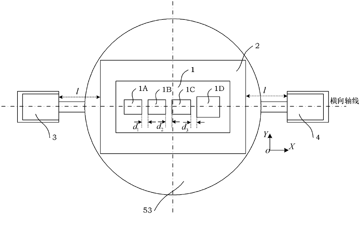
[0077] Dimensions of B patch 1B: a B =19.8mm,b B =19.8mm, h B =0.018mm; distance d between A patch 1A and B patch 1B 1 = 2mm;

[0078] see Figure 1C As shown, the size of C patch 1C: a C =21.6mm,b C =21.6mm, h C =0.018mm; distance d between B patch 1B and C patch 1C 2 = 2mm; the distance between the feed point 10 of the antenna...


PUM


Abstract

The invention discloses a patch antenna for directional diagram and frequency scanning, which comprises four patches, a dielectric plate, a metal plate, an electromagnet A, an electromagnet B and a turntable. The four patches are arranged in parallel on the metal plate, the metal plate is arranged on the dielectric plate, and the dielectric plate is arranged on the upper platform of the turntable. The electromagnet A is arranged on the platform of a connecting arm A of the turntable, and the electromagnet B is arranged on the platform of a connecting arm B of the turntable. The four patches are designed as a rectangular metal patch structure, so that the antenna is planar, small and light. The patch antenna is characterized in that the dielectric layer adopts ferrite, and the antenna frequency scanning is realized by adopting the spinning magnetism, precession and other related properties of the ferrite. Moreover, the antenna frequency scanning can be realized through adjusting a spinning column in an antenna mount, the adjustment is convenient, and the implementation is easy.

Description

technical field [0001] The present invention relates to a patch antenna, more particularly, it refers to a ferrite-based characteristic, which can realize the high and low frequency conversion of the antenna working frequency band only by rotating the platform, so as to realize the frequency sweep of the antenna, and is widely used It is used in wireless communication, radar and other fields that require reconfiguration of operating frequency. Background technique [0002] Yagi antenna, also known as directional antenna, is an antenna jointly developed and invented by Yagi Hideji and Uda Shintaro of Tohoku University in Japan in the 1920s, so it is called Yagi-Uda antenna, or Yagi antenna for short. [0003] Because the Yagi antenna has good directivity and has higher gain than the dipole antenna, it is widely used in radio equipment such as meter wave and decimeter wave band communication, TV, etc., for distance measurement and long-distance communication . In recent year...

Claims


Application Information

Patent Timeline
Patent Type & Authority Patents(China)
IPC IPC(8): H01Q5/00H01Q3/02H01Q1/38H01Q1/12H01Q5/30
Inventor 赵小莹丁忆涵
Owner BEIHANG UNIV
Why Eureka
Try Eureka