Icing sensor system and method

A technology of sensors and processors, applied in de-icing devices, aircraft parts, investigation phases/state changes, etc., can solve problems such as ineffectiveness

Inactive Publication Date: 2012-05-02
PENNY & GILES AEROSPACE
View PDF1 Cites 22 Cited by
  • Summary
  • Abstract
  • Description
  • Claims
  • Application Information

AI Technical Summary

Problems solved by technology

Traditional icing detectors become especially ineffectiv

Method used


Image

  • Icing sensor system and method
  • Icing sensor system and method
  • Icing sensor system and method

Examples


Embodiment Construction

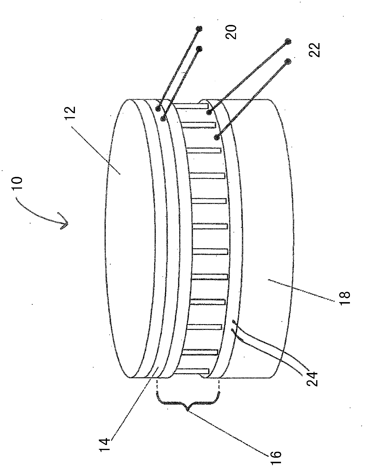
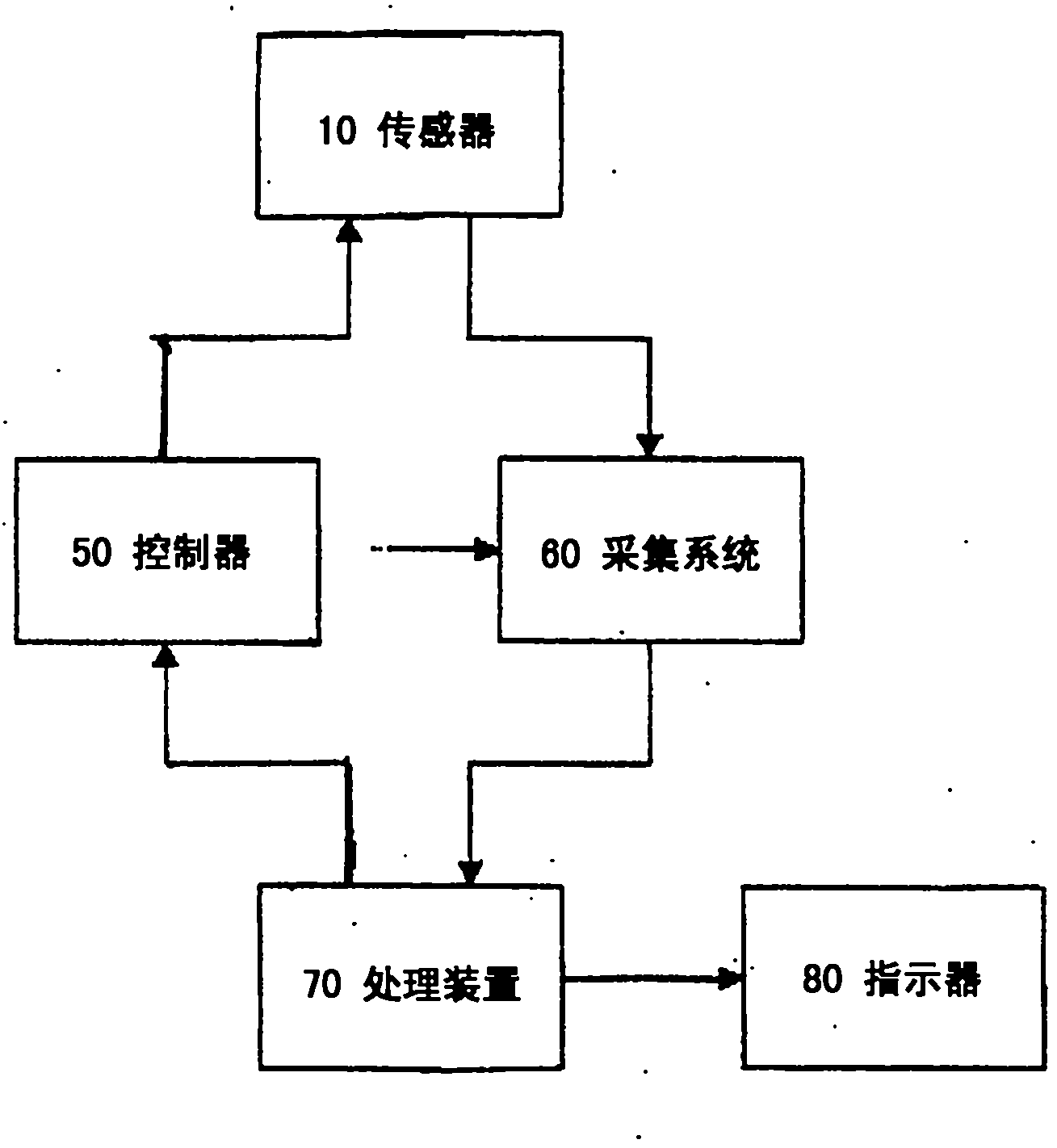
[0059] refer to figure 1 , the sensor device 10 includes a surface 12 that is exposed to the surrounding environment. The sensor device 10 also includes means 16 for cooling or heating the exposed surface 12 . This is a bidirectional heat pump 16 , such as a Paltre heat pump, and is electronically controlled by a controller (not shown) via heat pump wires 22 . A radiator 18 suitable for use with the heat pump 16 is provided to dissipate heat into the surrounding controls or into the aircraft structure. A temperature detector 14 forming part of or immediately behind surface 12 outputs a temperature reading indicative of the temperature of surface 12 via temperature sensing line 20 to an acquisition system (not shown). Outer surface 12 may be formed from a material that provides physical protection to sensor 10 and / or temperature detector 14 (eg, protects them from abrasion). Outer surface 12 may be part of sensor 10 or temperature detector 14 , or may be a protective coverin...


PUM


Abstract

In a first aspect the invention relates to a sensor system (10) for determining a proximity to icing conditions of an environment. The system includes a sensor having a sensor surface (12) for exposure to the environment, an electrically powered heat pump means (16) for cooling and/or heating the surface (12), and a temperature detector (14) for providing a signal representative of the temperature of the surface (12). An environment temperature is determined, and a processor determines, from the temperature detected by the temperature detector (14) and the environment temperature, a proximity to icing conditions of the environment to which the surface (12) is exposed. In a second aspect of the invention the sensor system includes a power monitor for determining an amount of power required to heat or cool the surface through a temperature indicative of ice formation. The processor determines the proximity to icing conditions from the detected temperatures and the amount of cooling or heating power.

Description

technical field [0001] The present invention relates to sensor systems and methods for detecting ice formation, and more particularly to sensor systems and methods for determining how close current conditions are to conditions where ice will form on a surface. Background technique [0002] In aircraft, ice buildup on wings, propellers, engine blades, control surfaces, etc., can create difficulties for pilots by adversely affecting aircraft control. Whether ice will form depends on local environmental conditions, such as atmospheric temperature, pressure and moisture content, and the speed of the aircraft. Traditionally, icing detectors have been used which typically monitor for the presence of ice on the exterior surfaces of the aircraft in order to generate an indication or warning of the presence of an icing condition. The disadvantage is that these devices can only detect icing once ice has started to form. They cannot determine how close the current state is to icing, ...

Claims


Application Information

Patent Timeline
IPC IPC(8): B64D15/20G01N25/04
CPCB64D15/20G01N25/68
Inventor 威廉姆·佩尼尼古拉斯·基德
Owner PENNY & GILES AEROSPACE
Why Eureka
Try Eureka