Movable feed hopper of tube-sinking cast-in-place pile and construction method

A technique of sinking cast-in-situ piles and feeding hoppers, which is applied to sheet pile walls, foundation structure engineering, construction, etc., and can solve problems such as increased force of concrete lateral extrusion, increased possibility of segregation, and reduced concrete quality , to achieve the effects of reducing the drop height, saving materials, and reducing the filling coefficient

Active Publication Date: 2014-01-22
HOHAI UNIV +1
View PDF5 Cites 0 Cited by
  • Summary
  • Abstract
  • Description
  • Claims
  • Application Information

AI Technical Summary

Problems solved by technology

[0004] (1) The feed hopper is fixed to the pile formwork, and its position gradually rises as the pile formwork is pulled out, so that the concrete must be transported to the height of the feed hopper when the concrete is poured. When the pile formwork is almost completely pulled out, the feed hopper The height from the ground is often 20-30m. At this time, the concrete must be transported to a height of 20-30m, so the energy of transporting concrete is wasted, time is wasted, the operation is inconvenient, and the concrete is easy to be lost during transportation.
[0005] (2) Concrete falls from a very high position, which increases the possibility of segregation and reduces the quality of concrete
[0006] (3) The concrete falling from a high place has a certain impact energy, which increases the lateral extrusion force of the concrete that has been poured into the foundation, and causes the concrete to squeeze and deform the soil around the pile hole, increasing the filling coefficient. wasted material

Method used


Image

  • Movable feed hopper of tube-sinking cast-in-place pile and construction method
  • Movable feed hopper of tube-sinking cast-in-place pile and construction method
  • Movable feed hopper of tube-sinking cast-in-place pile and construction method

Examples


Embodiment Construction

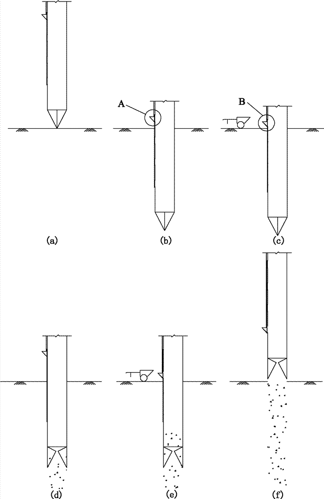
[0046] A movable feeding hopper and a construction method of a pipe-immersed cast-in-situ pile according to the present invention are not only suitable for pipe-immersed cast-in-situ piles with circular pile forms (such as solid piles and pipe piles), but also suitable for immersed pipe-grown piles with special-shaped cross-sections ( Such as X-shaped piles, Y-shaped piles, cross-shaped piles, etc.). This implementation example takes a circular sunk pipe cast-in-place pile as an example, but the scope of protection is not limited to the description of this implementation example.

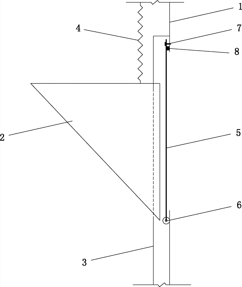
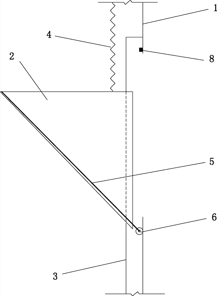
[0047] Such as figure 1 ~ As shown in Figure 7, a movable feeding hopper for immersed pipe pouring piles, two guide rails (3) in the vertical direction are arranged on the outer wall of the pile formwork (1), and the guide rails (3) are welded by two "L"-shaped steel materials On pile formwork (1) (such as Figure 4 and Figure 5 ), the bending section is on the outside. The two guide rails (3) ...


PUM


Abstract

The invention discloses a movable feed hopper of a tube-sinking cast-in-place pile and a construction method. A vertical guide rail is arranged on the outer surface of a pile formwork, the feed hopper is connected with the guide rail through connecting edges extending from the left side and the right side of the feed hopper, the upper portion of the feed hopper is connected with a hauling rope and the feed hopper can slide vertically along the guide rail. Two or more feed inlets are arranged on the pile formwork at a certain interval and disposed along the pile formwork. Openable cover plates are arranged outside the feed inlets and attached to the outer wall of the pile formwork when the pile formwork sinks into the foundation, and are opened when the pile formwork is pulled out and concrete needs to be poured, and sealing strips are arranged among the inner edges of the cover plates and the pile formwork. The construction method includes steps of taking the pile formwork to the place, sinking the pile formwork, moving the feed hopper downwards, opening one of the cover plates of the feed inlets, pouring the concrete, pulling the pile formwork upwards, moving the feed hopper downwards again, opening the next cover plate of the feed inlets, pouring the concrete and repeating the above processes until a pile is formed after the pile formwork is completely pulled out. The movable feed hopper is simple and convenient in operation, construction efficiency is improved, energy is saved and pile forming quality is guaranteed.

Description

technical field [0001] The invention belongs to the technical field of civil construction engineering, and in particular relates to a movable feeding hopper and a construction method of an immersed pipe grouting pile. Background technique [0002] Immersed tube pile is a commonly used pile foundation technology in civil engineering. It uses hammering pile driving equipment or vibrating pile driving equipment to sink steel pipes with prefabricated reinforced concrete pile tips or valve-type pile shoes into the soil. In the process, the pile hole is formed, and then the reinforced skeleton is put in and the concrete is poured through the fixed feeding hopper set on the pile formwork, and the concrete is poured while the pipe is pulled out while vibrating, and the concrete is compacted by the vibration during the pipe pulling, and the required concrete is formed. cast-in-place piles. [0003] Before the present invention, circular immersed pipe pouring piles, cast-in-place con...

Claims


Application Information

Patent Timeline
Patent Type & Authority Patents(China)
IPC IPC(8): E02D15/04E02D5/38
Inventor 丁选明陈育民刘汉龙孔纲强庄妍
Owner HOHAI UNIV
Why Eureka
Try Eureka