Coal power plant controllable type heat pipe flue gas waste heat recovery system and method

A flue gas waste heat recovery system technology, applied in combustion methods, preheating, feed water heaters, etc., can solve problems such as increasing layout space, fouling of equipment, affecting heat exchange efficiency, etc., reducing workload and easy disassembly. The effect of replacing and saving water resources

Inactive Publication Date: 2012-05-09
辽宁赛沃斯节能技术有限公司
View PDF5 Cites 12 Cited by
  • Summary
  • Abstract
  • Description
  • Claims
  • Application Information

AI Technical Summary

Problems solved by technology

[0014] ⑴Low-pressure economizer technology has a single heating medium
In other words, the low-pressure economizer cannot directly heat other working fluids, and recover the heat of the flue gas to other systems in the power plant that require more waste heat;
[0015] (2) Low-pressure economizer technology uses sensible heat transfer to recover heat, which is several orders of magnitude lower than latent heat transfer. At the same time, the inlet temperature of the heating medium is required to be high. Due to the high inlet temperature of the refrigerant, the heat exchange equipment is limited. Therefore, in the case of the same recovered heat, the smaller heat transfer temperature difference and lower heat transfer efficiency determine that a larger heat transfer area needs to be designed, which not only increases the layout space, but also increases the equipment investment;
[0016] (3) In order to save the layout space, the low-pressure economizer still adopts spiral finned tubes, but it is inevitable that there will be sticky ash deposits in the flue gas condensation area. These ash deposits are usually deposited at the fin intervals and are difficult to clean, even if soot blowers are installed The device is also difficult to remove. Over time, it will definitely affect the heat exchange efficiency, and it will also lead to an increase in the acid concentration around the pipe wall, which will intensify the corrosion;
[0017] ⑷The low-pressure economizer is a serpentine tube row connected to the inlet and outlet headers. It is an integral heat exchanger. If there is a corrosion leak in the tube bundle, the entire system must stop working immediately. If the entire system is not isolated in time, A large amount of soda and water will leak into the flue gas system, resulting in dust accumulation and corrosion of subsequent equipment, increased fan load, and increased power consumption. In severe cases, the desulfurization system cannot operate
[0019] (1) Poor energy saving: In the process of wet desulfurization of coal-fired boilers, the heat of flue gas at the boiler outlet is basically not recycled, and the operating energy consumption is increased;
[0020] In the low-pressure economizer technology, since the low-pressure economizer cannot directly heat other working fluids, it cannot recover the heat of the flue gas to other systems in the power plant that require more waste heat; the sensible heat transfer method is used to recover heat, which is better than the latent heat transfer The recovery efficiency is several orders of magnitude lower; in order to save the layout space, spiral finned tubes are still used, and it is inevitable that there will be sticky dust in the flue gas condensation area, and it is difficult to clean, which will affect the heat exchange efficiency;
[0021] (2) Poor environmental protection: In the process of wet desulfurization of coal-fired boilers, the operating energy consumption and environmental protection discharge pressure are relatively large;
[0022] (3) High cost: In the low-pressure economizer technology, sensible heat transfer is used to recover heat, and the inlet temperature of the heating medium is required to be high, while the high inlet temperature of the refrigerant limits the heat transfer temperature difference of the heat exchange equipment. In the case of the same amount of heat, a smaller heat transfer temperature difference and lower heat transfer efficiency require a larger heat transfer area and increase equipment investment;
[0023] In addition, in order to save the layout space, spiral finned tubes are still used. In the flue gas condensation area, there will inevitably be sticky ash deposits and it is difficult to remove, which will lead to an increase in acid concentration around the tube wall, intensified corrosion, and increased equipment maintenance. and replacement costs;
[0024] (4) Poor reliability: In the low-pressure economizer technology, the serpentine tubes connected to the inlet and outlet headers form an integral heat exchanger. If there is any corrosion and leakage in the tube bundle, the entire system must stop working immediately;
[0025] At the same time, if the entire system is not isolated in time, a large amount of soda water will leak into the flue gas system, resulting in dust accumulation and corrosion of subsequent equipment, increased fan load, and increased power consumption. In severe cases, the desulfurization system cannot operate;
[0026] ⑸Large space occupation: In the low-pressure economizer technology, sensible heat transfer is used to recover heat, and the inlet temperature of the heating medium is required to be high. Since the high inlet temperature of the refrigerant limits the heat transfer temperature difference of the heat exchange equipment, therefore, in In the case of the same recovered heat, a smaller heat transfer temperature difference and lower heat transfer efficiency require a larger heat transfer area and increase the layout space

Method used


Image

  • Coal power plant controllable type heat pipe flue gas waste heat recovery system and method
  • Coal power plant controllable type heat pipe flue gas waste heat recovery system and method
  • Coal power plant controllable type heat pipe flue gas waste heat recovery system and method

Examples


Embodiment Construction

[0067] The preferred embodiments of the present invention will be described below in conjunction with the accompanying drawings. It should be understood that the preferred embodiments described here are only used to illustrate and explain the present invention, and are not intended to limit the present invention.

[0068] System embodiment

[0069] According to an embodiment of the present invention, such as Figure 2a-Figure 5b As shown, a coal power plant controllable heat pipe flue gas waste heat recovery system is provided.

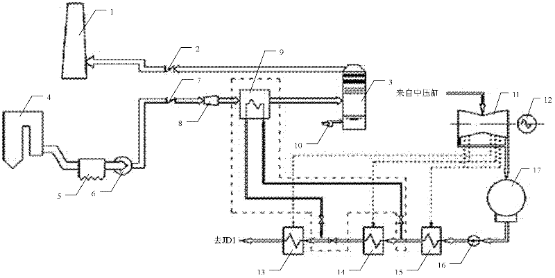
[0070] Such as image 3 As shown, this embodiment includes a boiler 4, a dust collector 5, an induced draft fan 6, a booster fan 8, a controllable heat pipe heat exchanger assembly, a desulfurization tower 26, and a chimney 1 that are sequentially connected through pipelines.

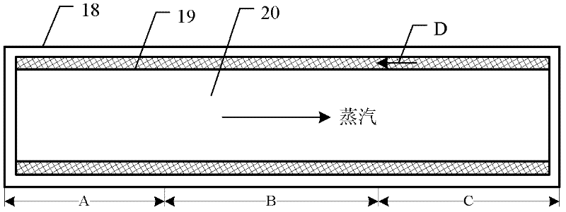
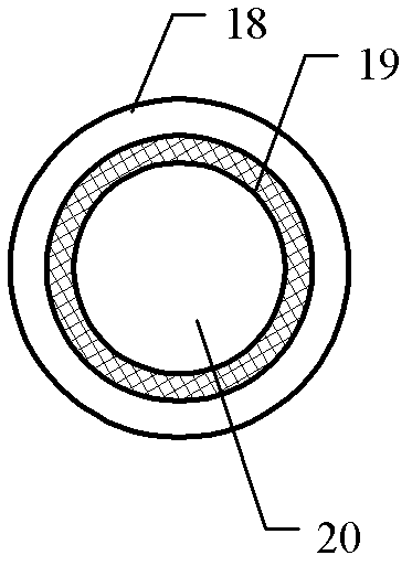
[0071] Here, in the controllable heat pipe heat exchanger assembly, the heat pipe is a high-efficiency heat exchange element that is filled with a working medium in the close...


PUM


Abstract

The invention discloses a coal power plant controllable type heat pipe flue gas waste heat recovery system and method. The system comprises a boiler, a deduster, a draught fan, a booster fan, a controllable type heat pipe heat exchanger component, a desulfurizing tower and a chimney which are sequentially connected in a cooperation mode through pipelines. The method comprises the following steps: additionally arranging the controllable type heat pipe heat exchanger component in a gas flue system of a coal power plant, and recycling heat and water vapor of the gas flue system; and a bypass gas flue is led out between the draught fan and the booster fan of the gas flue system and is connected between the desulfurizing tower and the chimney of the gas flue system. The coal power plant controllable type heat pipe flue gas waste heat recovery system and method disclosed by the invention can overcome the defects of poor energy conservation performance, poor environmental protection performance, high cost, poor reliability, large occupation space and the like so as to realize the advantages of good energy conservation performance, good environment protection performance, low cost, good reliability, small occupation space and wide application scope.

Description

technical field [0001] The invention relates to the technical field of energy conservation and environmental protection of coal power plants, in particular to a controllable heat pipe flue gas waste heat recovery system and method of coal power plants. Background technique [0002] In recent years, my country's energy demand has shown a rigid growth. Due to the constraints of domestic resource guarantee capacity and environmental capacity, as well as global energy security and the impact of climate change response, resource and environmental constraints have been increasingly strengthened, and the situation of energy conservation and emission reduction is very severe. [0003] According to my country's "Twelfth Five-Year Plan" put forward the requirements of energy conservation and emission reduction goals. In terms of energy saving, by 2015, the national energy consumption per 10,000 yuan of GDP will drop to 0.869 tons of standard coal (calculated at the price in 2005), whi...

Claims


Application Information

Patent Timeline
Patent Type & Authority Applications(China)
IPC IPC(8): F23J15/06F23L15/00F22D1/00
CPCY02E20/34
Inventor 陈建勤鄢常亮朱文颖于海东陈明
Owner 辽宁赛沃斯节能技术有限公司
Why Eureka
Try Eureka