Hybrid battery module and battery management method

A battery module and battery management technology, applied in battery electrodes, battery/fuel cell control devices, battery circuit devices, etc., can solve problems such as inability to supply power to loads, inability to charge each other, and inability to supply power to loads at the same time, to avoid loss, The effect of improving the service life

Inactive Publication Date: 2012-05-09
LITE ON CLEAN ENERGY TECH
View PDF4 Cites 31 Cited by
  • Summary
  • Abstract
  • Description
  • Claims
  • Application Information

AI Technical Summary

Problems solved by technology

In a series battery module, one group of batteries with stronger power is used to supply power to the load, while the other group of batteries is used to charge the battery for power supply, but cannot supply power to the load
In a parallel battery module, two sets of batteries can be selectively switched to supply power to the load, but the two cannot charge each other, nor can they supply power to the load at the same time

Method used


Image

  • Hybrid battery module and battery management method
  • Hybrid battery module and battery management method
  • Hybrid battery module and battery management method

Examples


no. 1 example

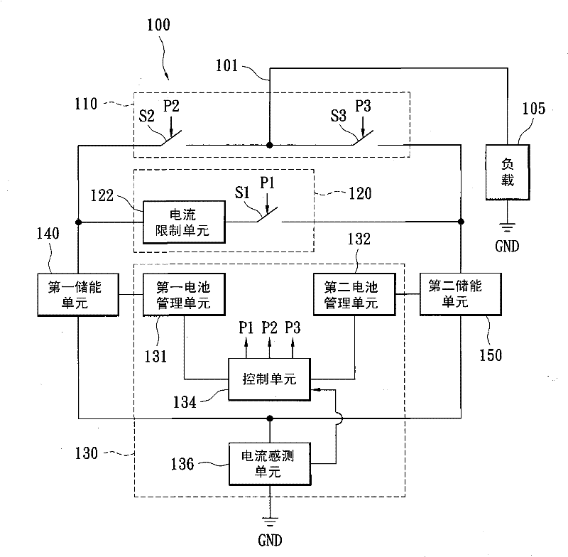
[0041] figure 1 It is a schematic diagram of the hybrid battery module according to the first embodiment of the present invention. The hybrid battery module 100 has a load terminal 101 which can be connected to a load 105 for power supply. The hybrid battery module 100 includes a power supply switching unit 110 , a charging unit 120 , a battery management circuit 130 , a first energy storage unit 140 and a second energy storage unit 150 . The power supply switching unit 110 has a switch S2 and a switch S3 , wherein the switch S2 is coupled between the first energy storage unit 140 and the load terminal 101 , and the switch S3 is coupled between the load terminal 101 and the second energy storage unit 150 . The charging unit 120 has a current limiting unit 122 and a switch S1 , wherein the current limiting unit 122 and the switch S1 are coupled in series between the first energy storage unit 140 and the second energy storage unit 150 . The battery management circuit 130 has a...

no. 2 example

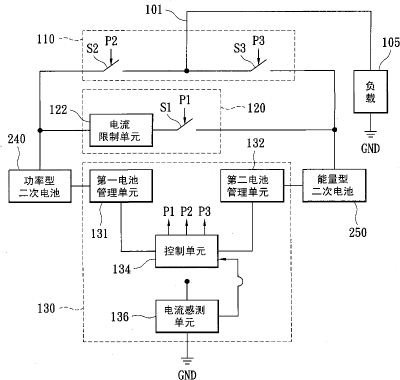
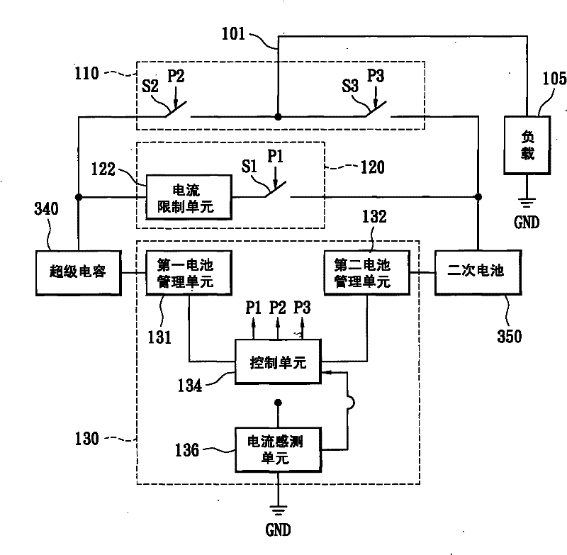
[0054] Please refer to image 3 , image 3 It is a schematic diagram of a hybrid battery module according to a second embodiment of the present invention. image 3 and figure 1 The main difference lies in the supercapacitor 340 and the secondary battery 350 . figure 1 The first energy storage unit 140 and the second energy storage unit 150 can be realized by using energy storage elements such as supercapacitors, such as image 3 shown. The supercapacitor 340 and the secondary battery 350 are respectively used to realize figure 1 The first energy storage unit 140 and the second energy storage unit 150 in the. Since the supercapacitor 340 has the effect of energy storage and rapid discharge, as long as the capacitance of the supercapacitor 340 is large enough, it can generate high-power output to drive the load 105 . The supercapacitor 340 is also called an ultra-large capacitor, such as an electric double-layer capacitor, but this embodiment is not limited thereto.

no. 3 example

[0056] the above figure 1 The current limiting unit 122 in can be replaced by a bidirectional DC-DC converter, such as Figure 4 as shown, Figure 4 It is a schematic diagram of a hybrid battery module using a bidirectional DC-DC converter 422 instead of the current limiting unit 122 . Figure 4 and figure 1 The main difference lies in the bidirectional DC-DC converter 422, which is coupled between the first energy storage unit 140 and the switch S1, and can be used for power conversion. The bidirectional DC-DC converter 422 can adjust the output power according to the state of charge, battery type and internal resistance of the first energy storage unit 140 and the second energy storage unit 150 to achieve the effect of energy transfer. For example, if a power-type secondary battery is used to charge an energy-type secondary battery, its bidirectional DC-DC converter 422 can control and adjust the power-type secondary battery using pulse width modulation (PWM) technology. ...


PUM


Abstract

The invention provides a hybrid battery module and a battery management method. The hybrid battery module is provided with a first energy storage unit, a second energy storage unit and a charging unit, wherein, the charging unit is coupled between the first energy storage unit and the second energy storage unit and is used for selectively providing a charging path between the first energy storage unit and the second energy storage unit so that the first energy storage unit charges the second energy storage unit or the second energy storage unit charges the first energy storage unit. In the invention, by adopting the charging unit, the first energy storage unit and the second energy storage unit can transfer energy to each other so as to maintain the best power status.

Description

technical field [0001] The invention relates to a battery module, and in particular to a hybrid battery module suitable for an electric vehicle and a battery management method thereof. Background technique [0002] With the continuous improvement of human awareness of environmental protection and energy conservation, electric vehicles have become the trend of future automobile development. Electric vehicles have the advantages of significantly reducing urban air pollution, and are quiet, zero pollution emissions, and do not need to use gasoline. Electric vehicles need to combine motor, machinery and battery technology, among which battery technology is the most important. Although the battery pack of an electric vehicle can provide the power required for vehicle acceleration, it is limited by the energy density (energy density, also called specific power) of the battery and its charging and discharging mechanism. How to increase the service life of the electric vehicle batt...

Claims


Application Information

Patent Timeline
Patent Type & Authority Applications(China)
IPC IPC(8): H02J9/06H02J7/00H01M10/42
CPCB60L11/005Y02T10/7066Y02T10/7022H02J7/0054H02J7/00B60L11/1864Y02T10/7061H02J7/0068H01M4/00H01M16/00Y02T10/7005B60L11/1868B60L50/40B60L58/21B60L58/20H02J7/342H02J2310/48Y02T10/70
Inventor 陈建志郑明旺
Owner LITE ON CLEAN ENERGY TECH
Why Eureka
Try Eureka