Vehicle brake device

A brake device, wheel brake cylinder technology, applied in the direction of the brake, can solve the number of parts, weight, cost increase and other problems, to achieve the effect of reducing the number of parts

Inactive Publication Date: 2012-05-09
HONDA MOTOR CO LTD
View PDF8 Cites 5 Cited by
  • Summary
  • Abstract
  • Description
  • Claims
  • Application Information

AI Technical Summary

Problems solved by technology

[0005] However, the above-mentioned prior art requires a pump for discharging the brake fluid accumulated in the reservoir, so there is a problem that the number of parts, weight, and cost increase due to the pump.

Method used


Image

  • Vehicle brake device
  • Vehicle brake device
  • Vehicle brake device

Examples


no. 1 approach

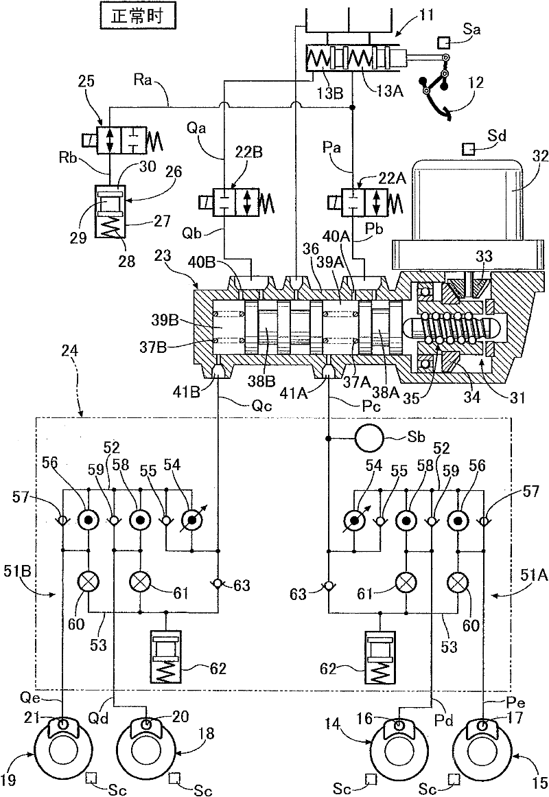
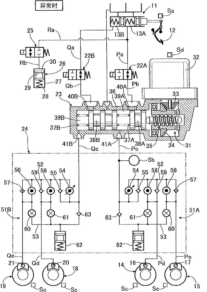
[0045] Such as figure 1 As shown, the tandem master hydraulic cylinder 11 includes rear and front hydraulic chambers 13A, 13B that output brake hydraulic pressure corresponding to the pedaling force of the driver stepping on the brake pedal 12, and the rear hydraulic chamber 13A passes through a fluid path Pa , Pb, Pc, Pd, Pe (first system) are connected to the wheel brake cylinders 16, 17 of the disc brake devices 14, 15 for the left front wheel and the right rear wheel, and the front hydraulic chamber 13B is connected via hydraulic The roads Qa, Qb, Qc, Qd, and Qe (second system) are connected to the wheel cylinders 20, 21 of the disc brake devices 18, 19 of the right front wheel and the left rear wheel, for example.

[0046] A shut-off valve 22A as a normally open solenoid valve is arranged between the liquid passages Pa and Pb, and a shut-off valve 22B as a normally open solenoid valve is arranged between the liquid passages Qa and Qb. Between the liquid passages Pb, Qb and th...


PUM


Abstract

A VSA device (24), which controls vehicle behavior by individually controlling the pressure of brake fluid supplied from a slave cylinder (23) to a wheel cylinder (16, 17; 20, 23), is provided with: an accumulator (62) which can be connected to the wheel cylinder and the slave cylinder (23); an out-valve (60, 61) disposed on a fluid path between the wheel cylinder and the accumulator (62); a check valve (63) that allows only flow of brake fluid from the accumulator (62) to the slave cylinder (23); and a regulator valve (54) disposed on a fluid path between the wheel cylinder and a path between the check valve (63) and the slave cylinder (23). Brake fluid is discharged from the accumulator (62) to the slave cylinder (23) by reducing the driving force of an electric motor (32) of the slave cylinder (23), thereby rendering a special pump unnecessary and making it possible to reduce the weight, cost, and component count.

Description

Technical field [0001] The present invention relates to a brake device for a vehicle, which includes: wheel brake cylinders that are provided for each wheel and generate braking force by brake hydraulic pressure; and the brake hydraulic pressure supplied to the wheel brake cylinders is generated by the operation of an electric motor The electric brake hydraulic pressure generating mechanism; is arranged between the electric brake hydraulic pressure generating mechanism and the wheel cylinders, and the braking of the vehicle behavior is controlled by separately controlling the brake hydraulic pressures supplied to the wheel cylinders Hydraulic control mechanism. Background technique [0002] The aforementioned vehicle brake device is known from Patent Document 1 below. [0003] This vehicle brake device is equipped with an ABS (Anti-Lock Braking System) device between the slave hydraulic cylinder and the wheel brake cylinder for suppressing the locking of the wheels and shortening ...

Claims


Application Information

Patent Timeline
Patent Type & Authority Applications(China)
IPC IPC(8): B60T8/17B60T8/00
CPCB60T8/42B60T8/4081
Inventor 波多野邦道
Owner HONDA MOTOR CO LTD
Why Eureka
Try Eureka