
Energy guiding chain

A technology of energy guiding chains and chain links, applied in the energy field of guiding cables, hoses or similar parts between connection points, which can solve problems such as damage to overlapping areas and achieve the effect of being easy to drop

Active Publication Date: 2012-05-09
IGUS
View PDF5 Cites 14 Cited by
  • Summary
  • Abstract
  • Description
  • Claims
  • Application Information

AI Technical Summary

Problems solved by technology

[0005] Although known chains are constructed in a closed manner, impurities with sharp edges, such as swarf, can still adhere to the surface of the chain links and get between the overlapping edges of adjacent chain links when the chain moves, where the impurities can Causes damage in the overlapping area and from there impurities can prepare to enter the interior of the chain

Method used


Image

  • Energy guiding chain
  • Energy guiding chain
  • Energy guiding chain

Examples


Embodiment Construction

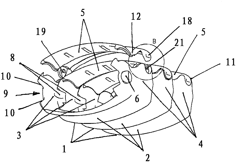
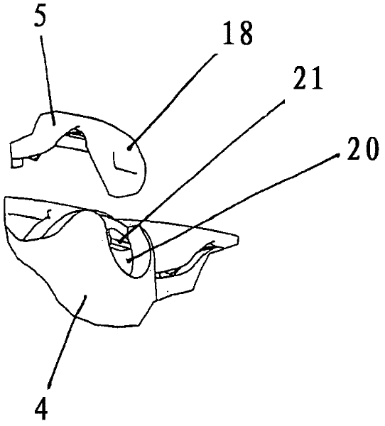
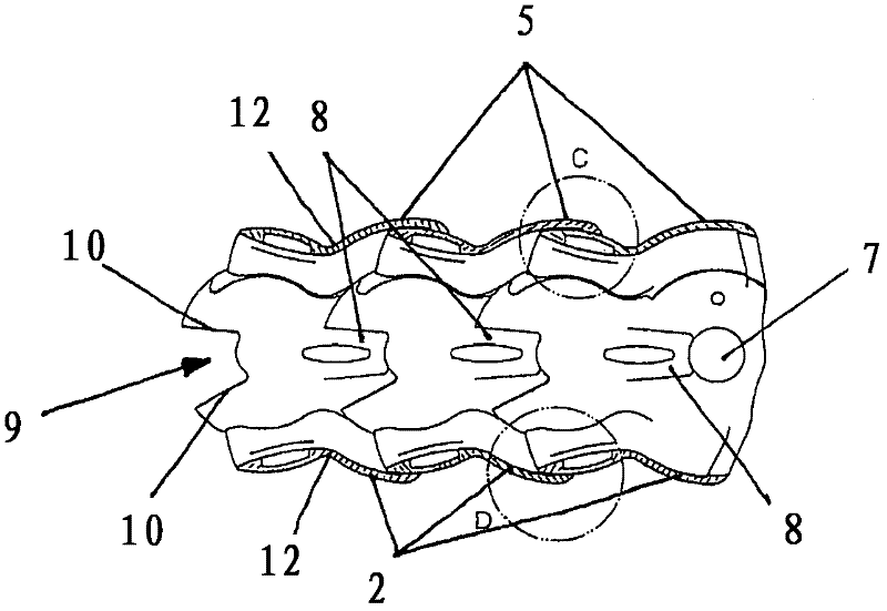
[0048] figure 1 A section of an energy guide chain consisting of three tubular chain links 1 is shown. Each chain link 1 comprises a bottom wall 2 , opposite side walls 3 and 4 adjoining the bottom wall, and a top wall 5 . from figure 1 The chain link 1 shown on the left shows that the top wall 5 can be removed from the side walls 3 and 4 in order to insert cables, hoses or the like into or out of the interior space of the energy guide chain. The bottom wall 2 is formed in one piece with the side walls 3 and 4 .

[0049] In order to connect the chain links 1 to each other in an articulated manner, the chain links 1 have at the end facing the longitudinal direction of the chain an outwardly protruding hinge pin 6 and at the opposite end a hinge opening 7 formed on its inner side, like figure 2 shown. The hinge opening 7 is designed as a blind hole, so that the hinge connection is covered by the overlapping area of ​​the side walls 3 and 4 after the joint of the chain link...


PUM


Abstract

The invention relates to an energy guiding chain for guiding cables, hoses and the like with a number of tubular chain links (1) connected together in an articulated manner and designed so that the surface of the top panels (5), bottom panels (2) and at least the transition areas (11) of these panels and the side panels (3, 4) are convexly curved in the circumferential direction of the tubular chain links (1), said chain links each having a bottom panel (5), comprising thereon laterally adjoining, opposite side panels (3, 4) and a top panel (5), whereupon the top panel (5) is detachably connected to the side panels (3, 4), the side panels (3, 4) in each case having a joint pin (6) and a joint opening (7) to connect flexibly, the pivoting angle of both directions of pivot being limited by stops (8) and the top panels (5), side panels (3, 4) and bottom panels (2); of adjacent chain links (1) overlapping telescopically over the entire pivoting angle.

Description

technical field [0001] The invention relates to an energy guide chain for guiding cables, hoses or the like between two connection points movable relative to one another, which comprises a plurality of articulated interconnected, tubular chain links, the chain The sections each comprise a bottom wall, opposite side walls adjoining the bottom wall, and a top wall removably connected to the side walls, the side walls respectively containing hinge pins and hinge openings for The adjacent chain links are hingedly connected, the deflection angles in the two deflection directions are limited by stoppers, and the top walls, side walls and bottom walls of the adjacent chain links overlap telescopically over the entire deflection angle. Background technique [0002] Such essentially closed energy-guiding chains are used in environments where there is a risk that impurities can penetrate the chain, for example in machine tools, in particular machines for cutting metal bodies, where ch...

Claims


Application Information

Patent Timeline
IPC IPC(8): H02G3/04H02G11/00
CPCH02G11/006F16G13/16H02G3/0475F16G15/12
Inventor T-A·耶克尔A·赫尔迈S·施特拉克M·奥弗纳
Owner IGUS
Learn More