Supercharge Your Innovation With Domain-Expert AI Agents!

Hanging device structure

A technology of hanger and hanging part, which is applied in the direction of supporting machines, other household appliances, household components, etc., and can solve problems such as large thread stress positive friction force, screw cannot move, laborious rotation and level adjustment, etc.

Inactive Publication Date: 2013-12-11
曾儒炯
View PDF5 Cites 0 Cited by
  • Summary
  • Abstract
  • Description
  • Claims
  • Application Information

AI Technical Summary

Problems solved by technology

[0006] First, the movement of displacement adjustment is quite labor-intensive and time-consuming
Since the existing cabinet hanger 1a uses the threads on the horizontal adjustment screw 30a and the vertical adjustment screw 40a to generate relative rotational displacement between the corresponding screw holes of the hanger 20a to achieve horizontal and vertical adjustments, however, due to the The plate body itself has a considerable weight, and this weight is almost borne by the hanging part 20a, resulting in a considerable stress on the thread and a relatively large positive friction force, and the user must work very hard to rotate the screw rod horizontally with a tool 30a and the vertical adjustment screw 40a; and, each time the user rotates the horizontal adjustment screw 30a or the vertical adjustment screw 40a one turn, the screw can be advanced or lifted by one thread pitch, so the user only needs to adjust the horizontal adjustment for one hanger 1a. The screw 30a or the vertical adjustment screw 40a is rotated many times (often up to ten times) to achieve the desired horizontal displacement or vertical displacement. In this way, the process of adjusting all the hangers 1a of the entire cabinet to the ideal position It is bound to be quite laborious and time-consuming
[0007] Second, the adjustment screw is easily damaged
Due to the structural design of the existing cabinet hanger 1a, the thread of the vertical adjustment screw 40a bears almost the weight of all the cabinet panels (only a single stress point), so great stress and friction are generated on the thread, causing the thread It is easy to be deformed and damaged; users often turn the vertical adjustment screw 40a back and forth several times, and the screw is stuck in the screw hole and cannot move or the thread collapses. At this time, a new hanger must be replaced to continue the cabinet. Hanging operation
[0008] Third, since the horizontal adjustment screw 30a and the vertical adjustment screw 40a are located on two adjacent side surfaces of the installation surface, so when the hanger 1a is locked on the cabinet board, the horizontal adjustment screw 30a and the vertical adjustment screw 40a are aligned with the vertical adjustment screw 40a. The distance between the cabinet boards is quite close; for a commonly used hanger 1a with a thickness of 2 cm, the distance between the center of the horizontal adjustment screw 30a and the vertical adjustment screw 40a and the cabinet board is only about 1 cm, so Therefore, when the user rotates the horizontal adjustment screw 30a and the vertical adjustment screw 40a, the surface of the cabinet board is often accidentally scratched, resulting in flaws in the appearance of the cabinet; When adjusting the horizontal displacement and vertical displacement of hanger 1a, you must be more careful not to scratch the surface of the cabinet, which will increase the difficulty of adjustment

Method used


Image

  • Hanging device structure
  • Hanging device structure
  • Hanging device structure

Examples


Embodiment Construction

[0067] The detailed description and technical content of the present invention will be described as follows with the accompanying drawings, but the attached drawings are only for illustration purposes and are not intended to limit the present invention.

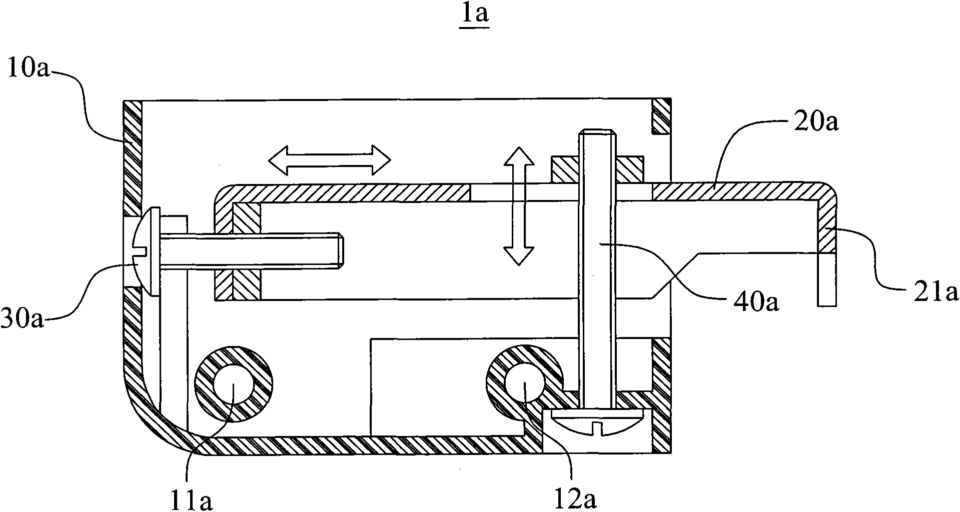
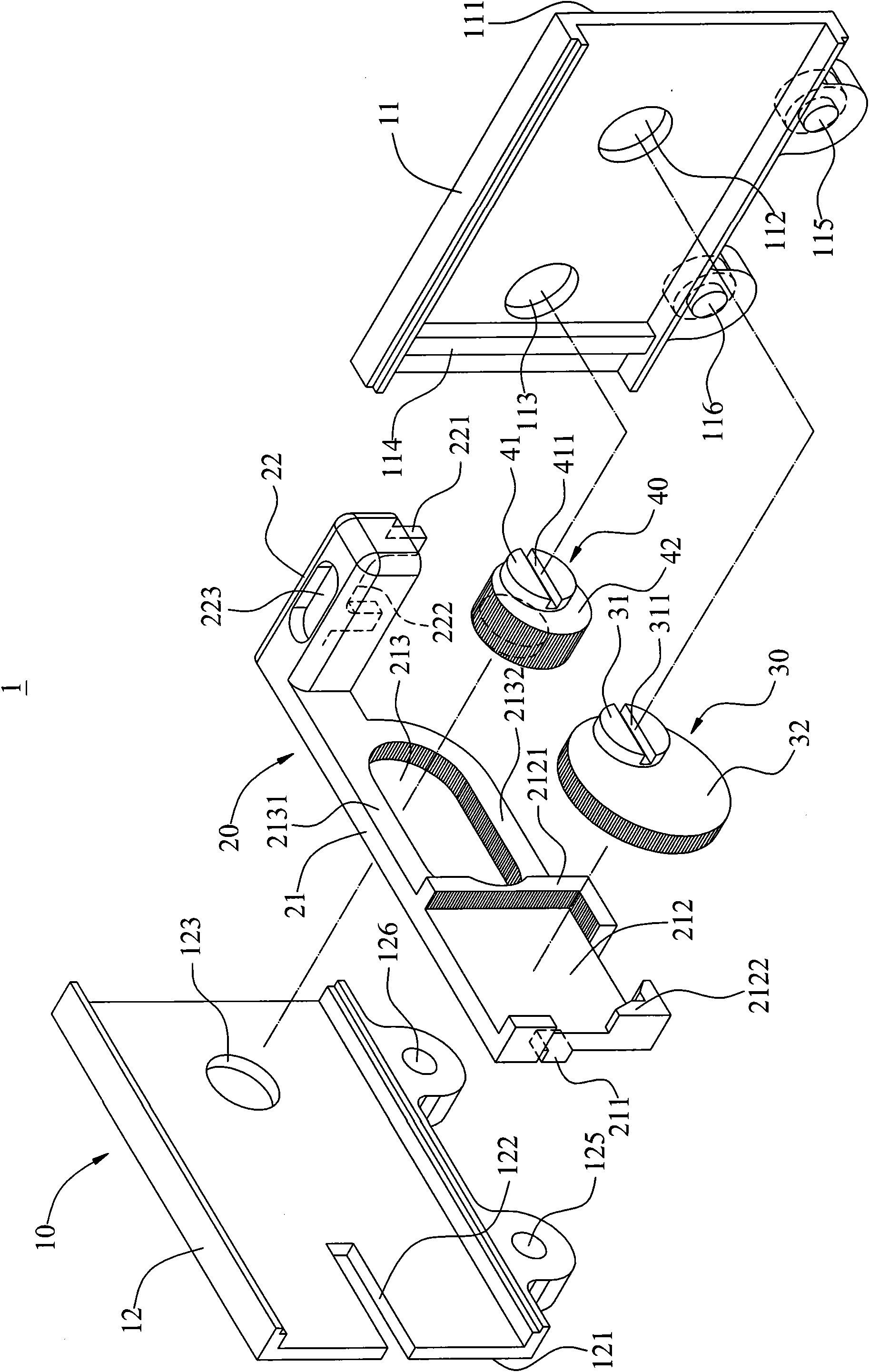
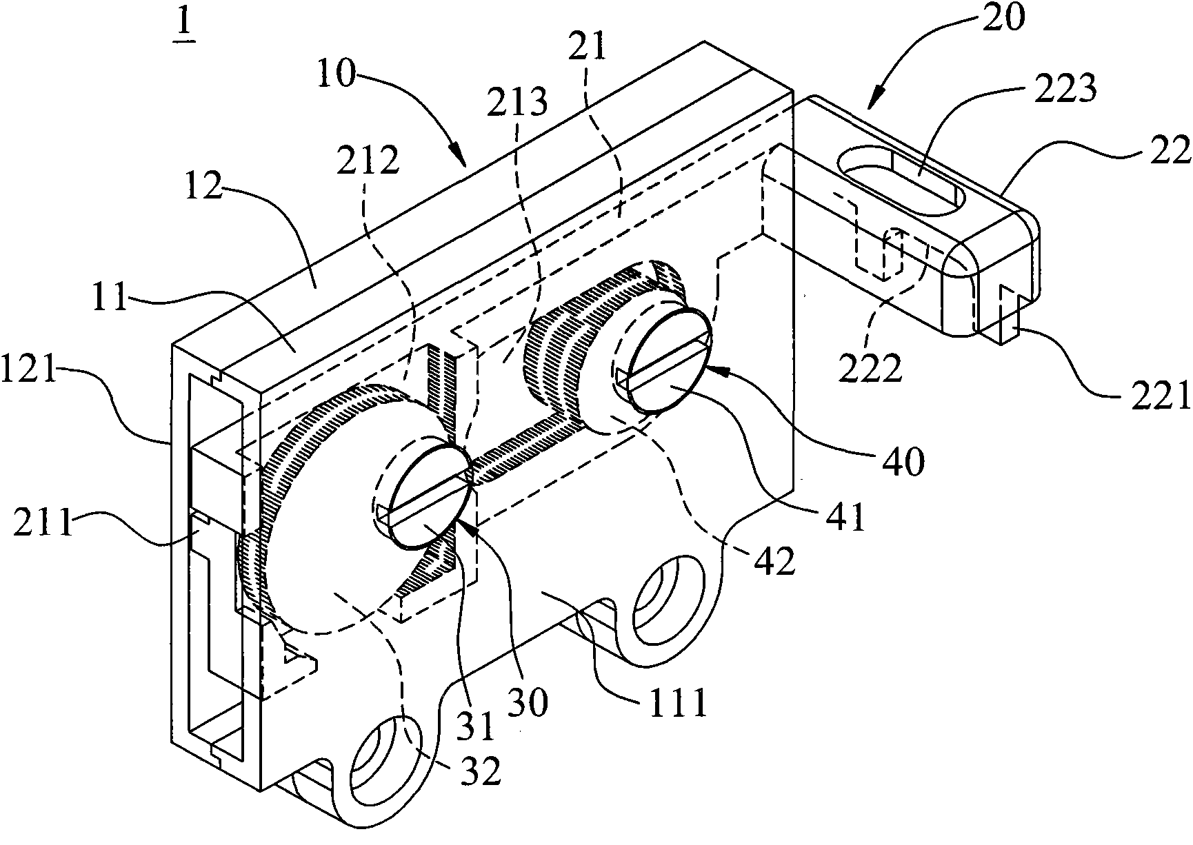
[0068] Please refer to Figure 2 to Figure 4 , the present invention provides a hanger structure 1 , the hanger structure 1 mainly includes: a housing 10 , a hanger 20 , a horizontal adjustment mechanism 30 and a vertical adjustment mechanism 40 . like Figure 8 and Figure 9 As shown, the hanger structure 1 is used to hang the cabinet 100 on the support 300 of the wall 200 .

[0069] exist figure 2 In the shown embodiment, the housing 10 is composed of a front shell 11 and a rear shell 12, the front shell 11 has an adjustment surface 111, a first hole 112 and a second hole 113, and the rear shell 12 has a mounting surface 121, a guide The guide groove 122 and the third hole 123; in other words, the housing 10 has an adj...


PUM


Abstract

The invention discloses a hanging device structure, which is used for hanging a cupboard on a support piece of a wall. The hanging device structure comprise a shell, a hanging piece, a first eccentric knob and a second eccentric knob, wherein the hanging piece comprises a main body part accommodated in the shell and a hanging part which is hung on the support piece by projecting forwardly from one end of the main body part to the outside of the shell; the first eccentric knob is used for adjusting the horizontal distance between the hanging part and the support piece; and the second eccentric knob is used for adjusting the vertical distance between the hanging part and the support piece. Due to the adoption of the hanging device structure, a user can adjust the horizontal displacement and vertical displacement of the hanging piece in a quick labor-saving way without damaging the surface of the cupboard.

Description

technical field [0001] The invention relates to a hanger structure, in particular to a hanger structure for hanging a cabinet on a wall. Background technique [0002] With the improvement of the quality of life, more and more families like to install cabinets on the walls of rooms or kitchens to achieve both storage and aesthetic effects. These cabinets are hung on designated on the wall surface. [0003] refer to figure 1 , shows the existing cabinet hanger. The hanger 1a commonly used in the market is roughly a rectangular block (thickness is about 2 cm), which mainly includes a rectangular shell 10a, which is arranged in the shell 10a and partially The hanger 20a protruding from the housing 10a, the horizontal adjustment screw 30a passing through the rear end of the hanger 20a, and the vertical adjustment screw 40a passing through the front end of the hanger 20a. The rectangular housing 10a has a mounting surface (not shown in the figure), which is used to lean against...

Claims


Application Information

Patent Timeline
Patent Type & Authority Patents(China)
IPC IPC(8): A47G29/087F16M13/02
Inventor 曾儒炯
Owner 曾儒炯
Features
  • R&D
  • Intellectual Property
  • Life Sciences
  • Materials
  • Tech Scout
  • Unparalleled Data Quality
  • Higher Quality Content
  • 60% Fewer Hallucinations
Learn More