Light-emitting vaginal dilator

A technology of vaginal expansion and luminous body, which is applied in the field of medical devices, can solve the problems of inconvenient adjustment, waste of manpower, and increased difficulty of operation, and achieve the effects of labor-saving adjustment of the opening angle, firm fixation, and easy operation

Inactive Publication Date: 2014-06-18
上海忆沐康医疗科技有限公司
View PDF8 Cites 6 Cited by
  • Summary
  • Abstract
  • Description
  • Claims
  • Application Information

AI Technical Summary

Problems solved by technology

Since the common adjustment mechanism is mostly a push button, which controls the opening and closing of the upper dilator and the lower dilator through the push button, it is inconvenient and laborious to adjust when using this method, and the common dilator does not have its own light source. In order to achieve a clear inspection Lesions can only be borrowed from external light sources, such as wearing reflectors on the forehead and flashlights, etc.
However, these two lighting methods have the following disadvantages: 1. Wearing reflectors on the forehead needs to be operated in a clinic with fixed spotlights. Because the light source is illuminated behind the operator's hand, it will produce angled shadows, which will increase visual difficulty for the operator. Affects the accuracy of diagnosis; 2. Need to take samples for testing or do minor surgery, and another person needs to use a flashlight or other light source to assist. Observing the lesions, not only wastes

Method used


Image

  • Light-emitting vaginal dilator
  • Light-emitting vaginal dilator
  • Light-emitting vaginal dilator

Examples


Embodiment 1

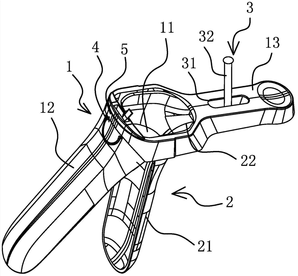
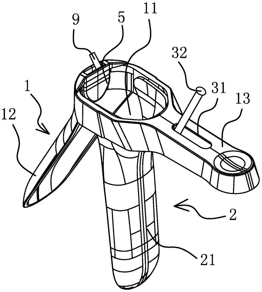
[0025] Such as Figure 1-3 As shown, the light-emitting vaginal dilator includes an upper half body 1 with a window 11, and the upper half body 1 has a duckbill-shaped upper blade 12 located on the upper side of the window 11 and an upper handle 13 located on the lower side of the window 11. , the lower half body 2 is hinged on the upper half body 1, and the lower half body 2 has a duckbill-shaped lower blade 21 and a lower handle 22 located inside the upper handle 13, and the upper blade 12 and the lower blade 21 are opposite and respectively located On the upper and lower sides of the window 11, between the upper handle 13 and the lower handle 22, a positioning mechanism 3 capable of controlling the opening angle of the upper blade 12 and the lower blade 21 is provided. The upper blade 12 has an installation gap 4 located at the window 11. The installation gap 4 is installed with a lamp holder shell 5, and the lamp holder shell 5 is provided with a light-transmitting hole 6 ...

Embodiment 2

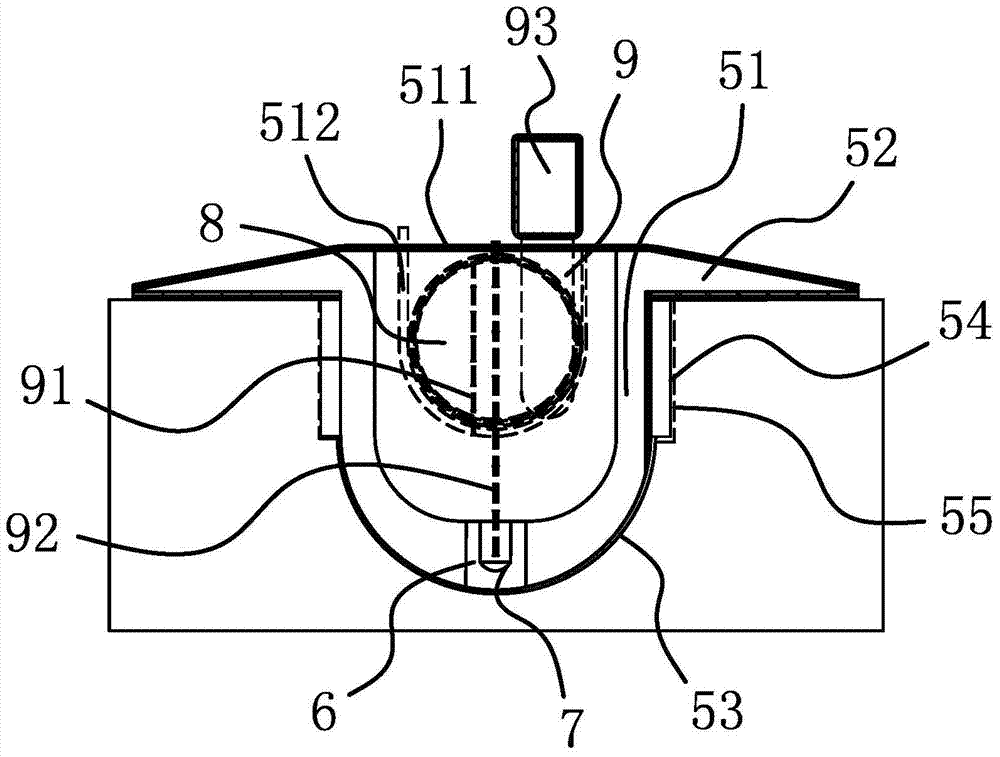
[0030] Such as Figure 4-5 As shown, the structure and principle of this embodiment are basically the same as that of Embodiment 1. The difference is that the positioning structure in this embodiment includes pin shafts 56 respectively arranged on both sides of the middle part of the box-shaped housing 51, and the installation gap 4 A pin hole 57 corresponding to the pin shaft 56 is provided on the top, and the pin shaft 56 is rotated and installed in the pin hole 57. The bottom of the extension part 52 is provided with an arc-shaped guide surface 58, and the end of the upper blade 12 has an arc-shaped The arc-shaped mating surface 59 matched with the guide surface 58 adopts a damping positioning structure so that the irradiation angle of the illuminant 7 can be adjusted during use, and no dead angle inspection in the vagina can be realized, and the use effect is better. In addition, the outer side of the upper blade 12 is provided with a limit block 121 integrated with the up...


PUM


Abstract

The invention relates to a light-emitting vaginal dilator. By adoption of the light-emitting vaginal dilator, the technical problems of no own light source and the like in the existing vaginal dilator are solved. The light-emitting vaginal dilator comprises an upper half body with a window, wherein the upper half body is provided with an upper blade and an upper handle; the lower half body is hinged to the upper half body and is provided with a lower blade and a lower handle; a positioning mechanism is arranged between the upper handle and the lower handle; an installing gap is arranged on the upper blade and is internally provided with a lamp holder shell; the lamp holder shell is provided with a light transmitting hole positioned at the inner end of the lamp holder shell; the lamp holder shell is internally and fixedly provided with a light emitting body and a battery; the light emitting body is connected with the battery, and a toggle switch is arranged between the light emitting body and the battery. The light-emitting vaginal dilator has the advantages that any external light source does not need to be used, the operation is easy, the entering of the sight line and surgical instruments is not easily blocked, starting or stopping of the light emitting body can be realized, the fixing of the light emitting body is firm, the illuminating angle is conveniently adjusted, and the battery is conveniently replaced, so that the use is convenient; by utilization of the lever principle, the adjustment of the opening angle is more labor-saving.

Description

technical field [0001] The invention belongs to the technical field of medical devices, in particular to a light-emitting vaginal dilator. Background technique [0002] At present, vaginal dilators are all used clinically when gynecological examinations, routine treatments and contraceptive measures are taken. Existing vaginal dilators are generally composed of two duckbill or olecranon-shaped upper and lower expansion pieces that can rotate around the pin shaft. The end of the upper expansion piece is provided with an observation window, and the upper expansion piece and the lower expansion piece are respectively connected with a second The first handle and the second handle are provided with an adjustment mechanism capable of adjusting the degree of opening and closing of the vaginal dilator between the first handle and the second handle. When in use, the opening angle of the upper and lower expansion pieces is adjusted through the adjustment mechanism , and then observe ...

Claims


Application Information

Patent Timeline
IPC IPC(8): A61B1/32A61B1/303A61B1/06
Inventor 焦大勇焦亚桂
Owner 上海忆沐康医疗科技有限公司
Why Eureka
Try Eureka