Energy recovery device for multi-stage pump

A multi-stage pump and flow technology, which is applied in the direction of pump devices, pumps, liquid displacement machinery, etc., can solve the problems of cavitation damage of the first stage impeller, and achieve the effect of avoiding cavitation damage and increasing pressure

Inactive Publication Date: 2012-05-16
SHANGHAI KAIQUAN PUMP IND GROUP
View PDF0 Cites 2 Cited by
  • Summary
  • Abstract
  • Description
  • Claims
  • Application Information

AI Technical Summary

Problems solved by technology

In the prior art, since the liquid is sucked into the pump completely depending on the negative pressure of the suction section of the multi-stage pump, it is easy to cause cavitation damage to the first-stage impeller

Method used


Image

  • Energy recovery device for multi-stage pump
  • Energy recovery device for multi-stage pump
  • Energy recovery device for multi-stage pump

Examples


Embodiment Construction

[0013] The preferred embodiments of the present invention are given below in conjunction with the accompanying drawings to describe the technical solution of the present invention in detail.

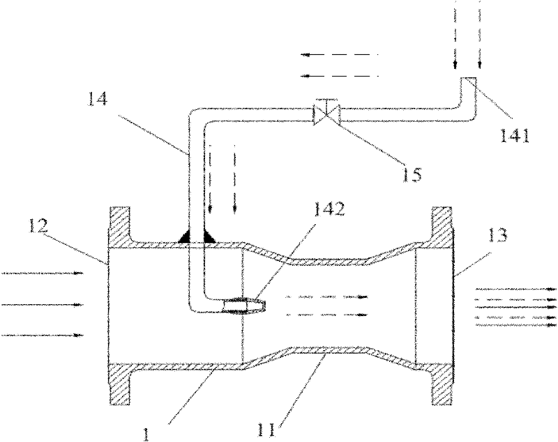
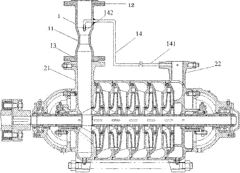
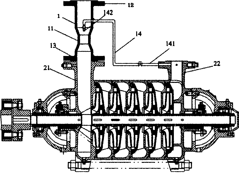
[0014] like figure 1 and 2 As shown, the energy recovery device in the present invention includes a hollow cylindrical flow mixer 1, which includes a liquid inlet 12 and a liquid outlet 13, located in the middle of the liquid inlet 12 and the liquid outlet 13 There is a pressurized section 11 constricting toward the center of the flow mixer 1 . The energy recovery device also includes a booster tube 14, one end 141 of the booster tube 4 is used to connect with the water discharge section 22 of the multi-stage pump, and the other end is passed through the inside of the flow mixer 1, and is located at the liquid inlet 12 and Between the pressurization sections 11 , at the end of the pressurization pipe 4 inside the flow mixer 1 is provided a nozzle 142 whose water outlet points to the pr...


PUM


Abstract

The invention discloses an energy recovery device for a multi-stage pump, which comprises a hollow columnar flow mixer and a pressurized pipe, wherein a liquid inlet is arranged at one end of the flux mixer, a liquid outlet is arranged at the other end of the flux mixer, a pressurized segment is arranged at the middle of the flux mixer, the pressurized pipe is used for collecting return liquid, one end of the pressurized pipe extends into the flux mixer and is provided with a nozzle, and the nozzle is positioned between the pressurized segment and the liquid inlet and faces the liquid outlet. By adopting the energy recovery device, high-pressure liquid obtained from a discharge segment of the multi-stage pump and liquid sucked by a liquid storage container of the multi-stage pump are mixed and then are sent to a suction segment, the kinetic energy of high-pressure water flow is transformed into pressure energy of the liquid in the suction segment, the pressure of the entrance of a first-stage impeller is increased, and the first-stage impeller is prevented from being cavitated and damaged due to extremely low pressure of the sucked liquid.

Description

technical field [0001] The invention relates to the field of pumps, in particular to an energy recovery device for multistage pumps. Background technique [0002] The multi-stage pump includes a liquid channel, which includes a suction section, a middle section and a discharge section, and the liquid enters from the suction section, flows through the middle section, and then flows out from the discharge section. The suction section communicates with the liquid storage container, and the discharge section communicates with the liquid-using equipment. There are several impellers coaxially inside the multi-stage pump, the first-stage impeller near the suction section, the second-stage impeller, the third-stage impeller, and the last-stage impeller in the discharge section in sequence along the liquid flow direction. In the prior art, since the liquid is sucked into the pump completely depending on the negative pressure of the suction section of the multi-stage pump, it is easy...

Claims


Application Information

Patent Timeline
Patent Type & Authority Applications(China)
IPC IPC(8): F04B23/14
Inventor 王者文施勇郗忠才
Owner SHANGHAI KAIQUAN PUMP IND GROUP
Why Eureka
Try Eureka