Friction clutch for automobile

A clutch and friction technology, applied in the field of clutches, can solve problems such as high maintenance costs, easy to wear clutch plates, and unfavorable durability, so as to achieve the effect of reducing maintenance rate, not easy to wear, and increasing service time

Inactive Publication Date: 2012-05-16
常州金盛永业车辆有限公司
View PDF0 Cites 8 Cited by
  • Summary
  • Abstract
  • Description
  • Claims
  • Application Information

AI Technical Summary

Problems solved by technology

[0003] The technical problem to be solved by the present invention is: the clutch plates are mostly used in a sliding state, and the clutch plates are easy to wear after the oil film between the clutch plates is exhausted, which is unfavorable to durability and has high maintenance costs. Friction clutches for cars

Method used


Image

  • Friction clutch for automobile
  • Friction clutch for automobile

Examples


Embodiment Construction

[0010] The present invention is described in further detail now in conjunction with accompanying drawing. These drawings are all simplified schematic diagrams, which only illustrate the basic structure of the present invention in a schematic manner, so they only show the configurations related to the present invention.

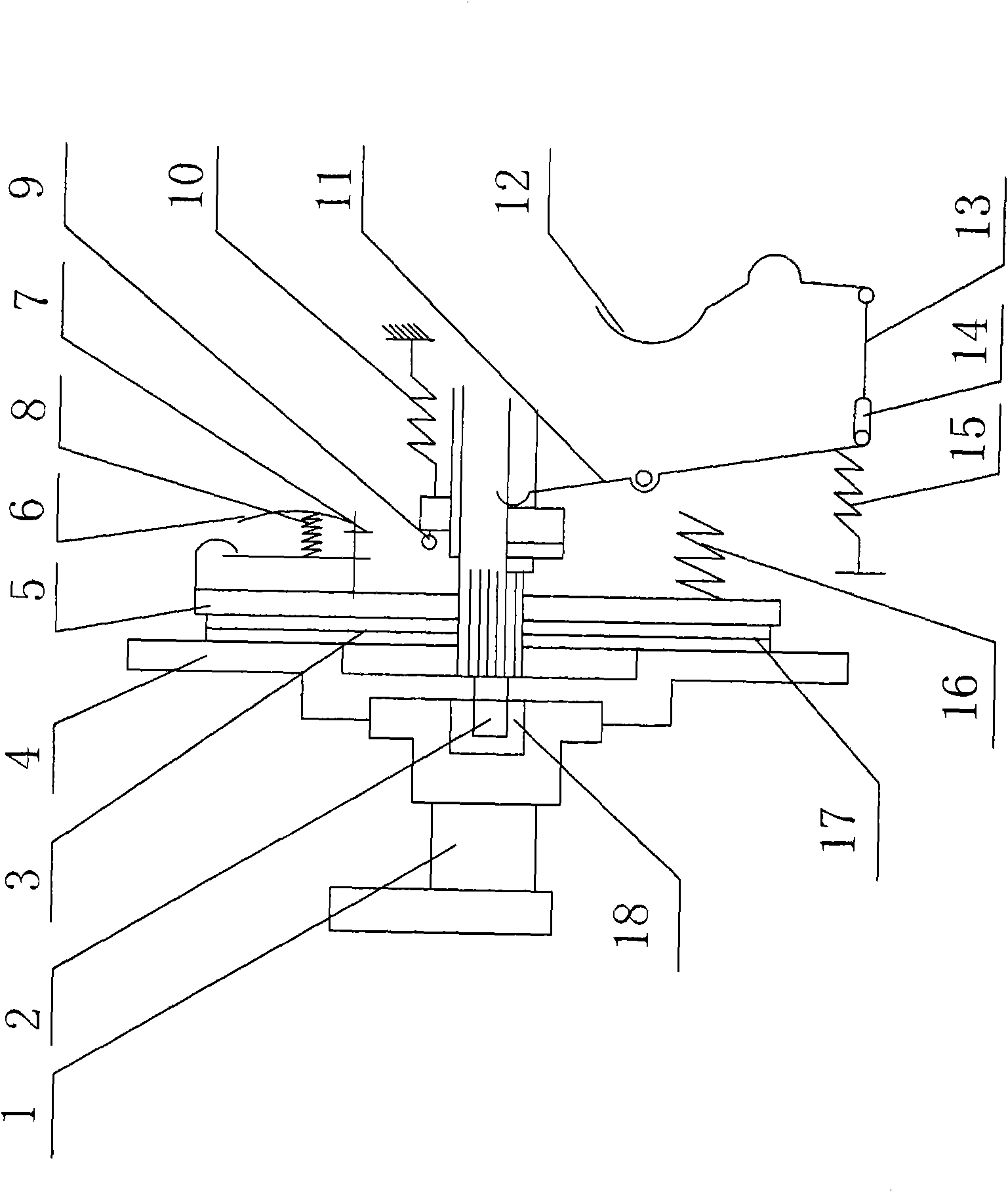
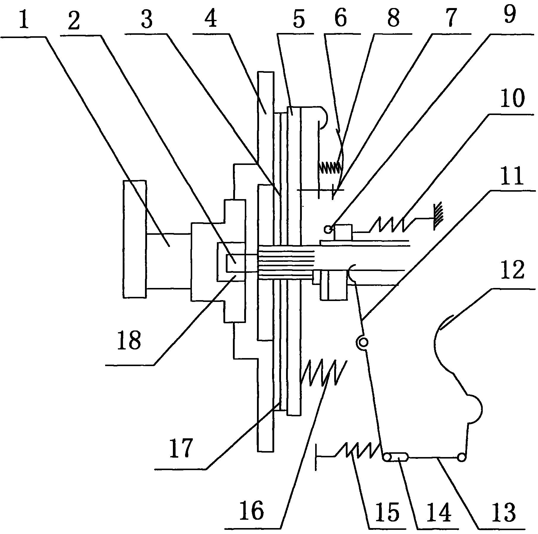
[0011] figure 1 It is a structural schematic diagram of the present invention, including crankshaft 1, driven shaft 2, driven plate 3, flywheel 4, pressure plate 5, clutch cover 6, release lever 7, spring 8, release bearing 9, return spring 10, release Shift fork 11, pedal 12, pull rod 13, pull rod adjustment fork 14, return spring 15, compression spring 16, driven disk friction plate 17 and bearing 18, described flywheel 4, pressure plate 5 and clutch cover 6 form clutch In the active part, the flywheel 4 is fixed with the crankshaft 1 by bolts, and the clutch cover 6 is fixed on the rear end surface of the flywheel 4 by screws. The driven disc friction plat...


PUM


Abstract

The invention relates to the technical field of automobiles, in particular to a friction clutch for an automobile. In the friction clutch, a drive part is composed of a flywheel, a press disc and a clutch cover, a driven part is composed of a driven disc friction plate, a driven disc and a driven shaft, a compaction device is composed of a press spring, a control mechanism is composed of a release lever, a release shift fork, a pedal, a pull rod, a pull rod adjusting fork, a return spring, a release bearing and a first return spring, the middle part of the release lever is supported on a fulcrum of the clutch cover. The friction clutch is simple in structure and is difficult to be abraded during practical application, the service time of the clutch is increased, the maintenance rate is reduced, and economic benefit is brought.

Description

technical field [0001] The invention relates to a clutch, in particular to a friction clutch for automobiles. Background technique [0002] As we all know, the clutch used in various traditional power transmission mechanisms is a multi-plate clutch, which is alternately arranged by multiple clutch plates that rotate integrally with the components on the input side and multiple clutch plates that rotate integrally with the components on the output side. , press each clutch plate mutually, utilize the frictional force of each clutch plate. Transmits the rotational force from the input side to the output side. Most of the clutch plates are used in a sliding state. After the oil film between the clutch plates is used up, it is easy to wear the clutch plates, which is not good for durability, and the maintenance cost is high. Contents of the invention [0003] The technical problem to be solved by the present invention is: the clutch plates are mostly used in a sliding state,...

Claims


Application Information

Patent Timeline
Patent Type & Authority Applications(China)
IPC IPC(8): F16D13/38F16D13/58
Inventor 徐寅
Owner 常州金盛永业车辆有限公司
Why Eureka
Try Eureka