
Device and method for reducing the energy consumption of an automation machine

A technology of energy consumption and machines, applied in the direction of instruments, general control systems, digital control, etc., can solve problems such as high energy consumption of machine tools

Inactive Publication Date: 2012-05-16
SIEMENS AG
View PDF5 Cites 0 Cited by
  • Summary
  • Abstract
  • Description
  • Claims
  • Application Information

AI Technical Summary

Problems solved by technology

Here, machine tools in particular have a very high energy consumption

Method used


Image

  • Device and method for reducing the energy consumption of an automation machine
  • Device and method for reducing the energy consumption of an automation machine
  • Device and method for reducing the energy consumption of an automation machine

Examples


Embodiment Construction

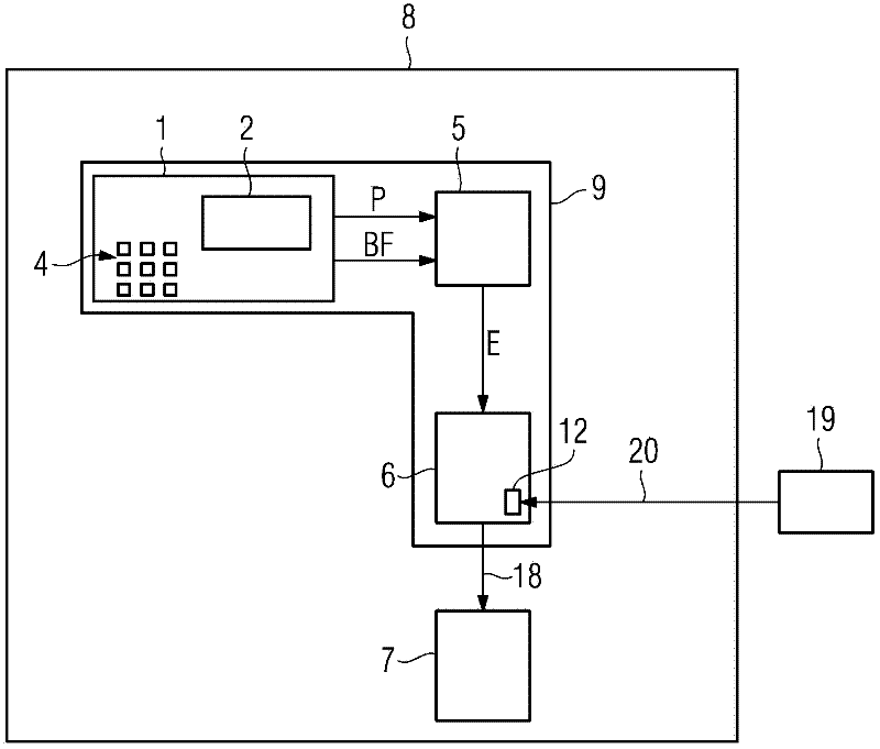
[0020] exist figure 1 An automated machine 8 with a device 9 according to the invention for reducing the energy consumption of the automated machine is shown in a schematic box-shaped illustration. The device 9 according to the invention exists here in the form of a CNC controller (Computer Numerical Control) within the scope of the exemplary embodiment, wherein for the sake of simplicity the figure 1 Only the elements of the CNC controller that are important for understanding the invention are shown in FIG. Within the scope of the exemplary embodiment, the device 9 according to the invention has an operating unit 1 , an evaluation unit 5 and a control unit 6 . The evaluation unit 5 and the control unit 6 are present within the scope of the exemplary embodiment in the form of executable software codes which are executed on one or more processors. The control unit 6 can be present, for example, in the form of an SPS (Programmable Controller Speicherprogramierbare Steuerung). ...


PUM


Abstract

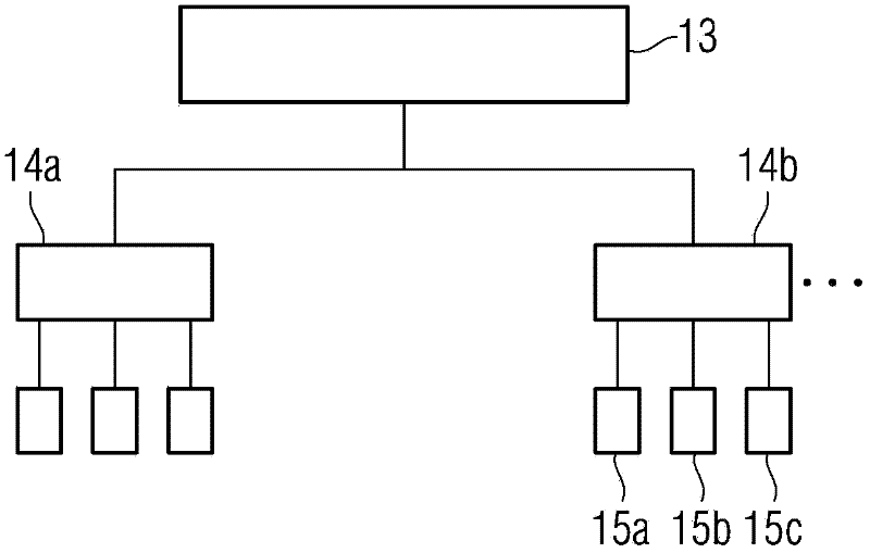
The present invention relates to a device for reducing energy consumption of an automation machine (8), wherein the device (9) is designed to a mode which is characterized in that: an operator can select operation types (14a,14b) of the machine (8) and operation functions (15a,15b,15c) which belong to the operation types (14a,14b), wherein the device (9) is designed so that the parameter (P) which belongs to the selected operation functions (15a,15b,15c) can be input. The device (9) is designed for measuring an energy consumption state (E) according to the selected operation functions (15a,15b,15c) and the parameter (P). Furthermore the invention relates to a related method. The device and the method of the invention can reduce energy consumption of the automation machine (8).

Description

technical field [0001] The invention relates to a device and a method for reducing the energy consumption of an automated machine. Background technique [0002] Automated machines such as machine tools, production machines and / or robots generally have a very high energy consumption. Machine tools in particular have a very high energy consumption here. Contents of the invention [0003] The object of the invention is to reduce the energy consumption of automated machines. [0004] This object is achieved by a device for reducing the energy consumption of an automated machine, wherein the device is designed in such a way that the operator can select the type of operation of the machine and the operating functionality belonging to this type of operation, wherein the device is designed in such a way that Parameters belonging to the selected operating functionality can be input, wherein the device is designed to determine the energy consumption state on the basis of the selec...

Claims


Application Information

Patent Timeline
Patent Type & Authority Applications(China)
IPC IPC(8): G05B19/18
CPCG05B19/042
Inventor 米歇尔·格施维尔安德烈亚斯·格勒辛格
Owner SIEMENS AG
Learn More