
Method for manufacturing dental instrument for regulating position of tooth

A technology for teeth and instruments, applied in the field of orthodontics, can solve the problems of difficult maintenance of oral hygiene, complicated orthodontic process, poor aesthetics and comfort, etc.

Active Publication Date: 2012-05-16
WUXI EA MEDICAL INSTR TECH
View PDF4 Cites 20 Cited by
  • Summary
  • Abstract
  • Description
  • Claims
  • Application Information

AI Technical Summary

Problems solved by technology

This method has the following disadvantages: poor aesthetics and comfort; oral hygiene is difficult to maintain; clinicians need a long period of training to gradually master the technology; doctors spend a lot of time adjusting the appliance for each follow-up visit, and the correction process is complicated
Its disadvantage is that once the final tooth state is determined, the intermediate tooth state is determined, so it is difficult to avoid tooth collision during orthodontics, and it is difficult to set the step size individually for different operations on the same tooth

Method used


Image

  • Method for manufacturing dental instrument for regulating position of tooth
  • Method for manufacturing dental instrument for regulating position of tooth
  • Method for manufacturing dental instrument for regulating position of tooth

Examples


example 1

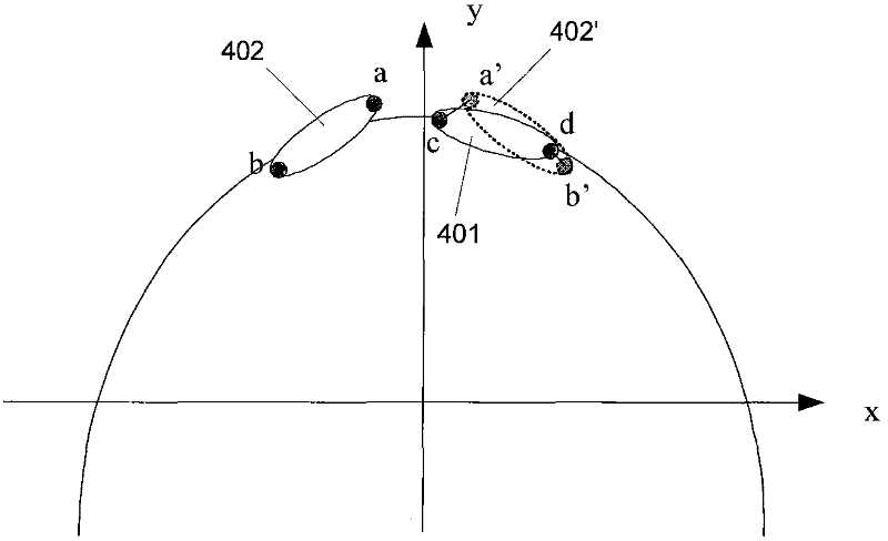
[0149] image 3 It is a schematic diagram of the maxillofacial upper incisors of Case 1, the tooth 401 is normal, the tooth 402 needs to rotate clockwise around the z-axis, and move positively along the x-axis, and may also need to move along the y-axis.

[0150] In this case, arch symmetry was used as an index of correction. In one embodiment, two reference points a and b can be taken on the tooth 402 , and correspondingly, two corresponding reference points c and d can also be taken on the tooth 401 . The tooth 402 is mapped with the y-axis as the axis of symmetry to obtain the tooth 402', as well as the reference points a' and b'. The symmetry is measured by the sum of the lengths of the straight lines a’c and b’d, the smaller the value, the higher the symmetry. In this example, it is assumed that the correction index data is that the sum of the lengths of a'c and b'd is less than 0.5 mm, that is, the sum of the lengths of the straight line a'c and b'd is less than 0.5 mm...

example 2

[0152] Figure 4a Maxillofacial view of Case 2, Figure 4b is the maxillary frontal view of Case 2, Figure 4c is the mandibular and maxillofacial view of Case 2, Figure 4d Frontal view of the mandible of Case 2.

[0153] In this case, tooth 521 is labially inclined, and the anterior teeth are deeply overbited. The position of tooth 511 is normal, and there is enough space between teeth 511 and 522 to accommodate tooth 521 . The orthodontic plan is that the teeth 521 are tilted lingually, the tongue is adducted, the positive axis is elongated, and the dentition is aligned. At the same time, the teeth 531 and 532 are depressed, and the occlusion is opened to cooperate with the movement of the teeth 521.

[0154] For the tooth 521, the tooth 511 may be used as a reference, and the orthodontic index data may include anterior overbite, anterior overlay, torque, axial inclination, distance between the incisal edge of the incisor and the occlusal plane, and the like.

[0155] ...


PUM


Abstract

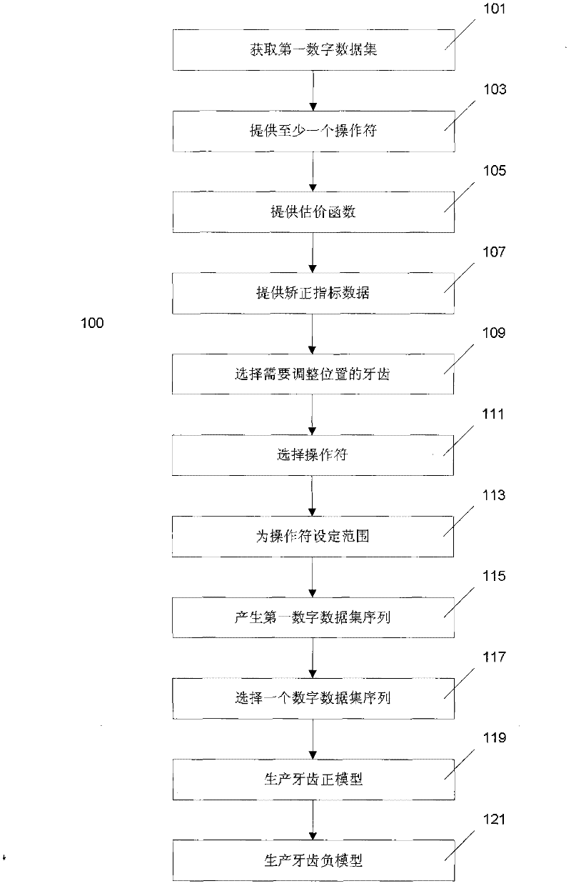
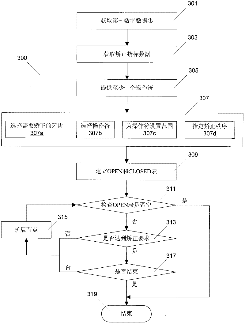
The invention discloses a method for manufacturing a dental instrument for regulating the position of a tooth, namely the method for generating a digital dataset which represents a tooth state. The method comprises the following steps of: acquiring a first digital dataset which represents a first tooth state; providing at least one operator for modifying the digital dataset which represents the tooth state; performing state space searching based on the first digital dataset by utilizing a state space searching method and the operator to obtain a second digital dataset which represents a second tooth state; obtaining an Nth digital dataset which represents an Nth tooth state by the same method, wherein N is an integer more than 2; and comparing the Nth digital dataset with correction index data to judge whether the Nth tooth state meets a correction index or not.

Description

technical field [0001] The present application relates to the field of orthodontics, in particular to a method for computer-aided manufacturing of dental instruments for adjusting the position of teeth. Background technique [0002] The traditional orthodontic treatment is to use orthodontic appliances such as arch wires, springs, and leather rings to correct teeth by bonding devices such as belt rings and brackets on the teeth. This method has the following disadvantages: poor aesthetics and comfort; oral hygiene is difficult to maintain; clinicians need a long period of training to gradually master the technology; doctors spend a lot of time adjusting the appliance for each follow-up visit, and the correction process is complicated. Compared with traditional bracket aligners, invisible orthodontic technology does not require brackets and arch wires, and uses a series of invisible aligners. This kind of invisible aligner is made of safe elastic transparent polymer material...

Claims


Application Information

Patent Timeline
IPC IPC(8): G06F17/50A61C7/00
Inventor 李忠科田杰
Owner WUXI EA MEDICAL INSTR TECH
Learn More