

Electronic apparatus, power feeding method, and power feeding system
An electronic device and power feeding technology, which is applied in the direction of circuit devices, electromagnetic wave systems, battery circuit devices, etc., can solve the problems of foreign metal heating and easy placement, and achieve the effect of preventing abnormal heating
- Summary
- Abstract
- Description
- Claims
- Application Information
AI Technical Summary
Problems solved by technology
Method used
Image

Examples
example 2
[0030] 3. Modified example 2 (case of foreign object detection operation using an oscillation circuit)
[0031] 4. Modified example 3 (the case where linear positive and negative electrodes are alternately arranged discretely)
[0032] 5. Modified example 4 (the case where grid-shaped positive and negative electrodes are alternately arranged discretely)
[0033] 6. Modified example 5 (case where comb-shaped positive and negative electrodes are arranged so as to mesh with each other)
[0034] 7. Modified example 6 (the case where the ring-shaped positive and negative electrodes are alternately arranged concentrically)
[0035]
[0036] [Overall structure]
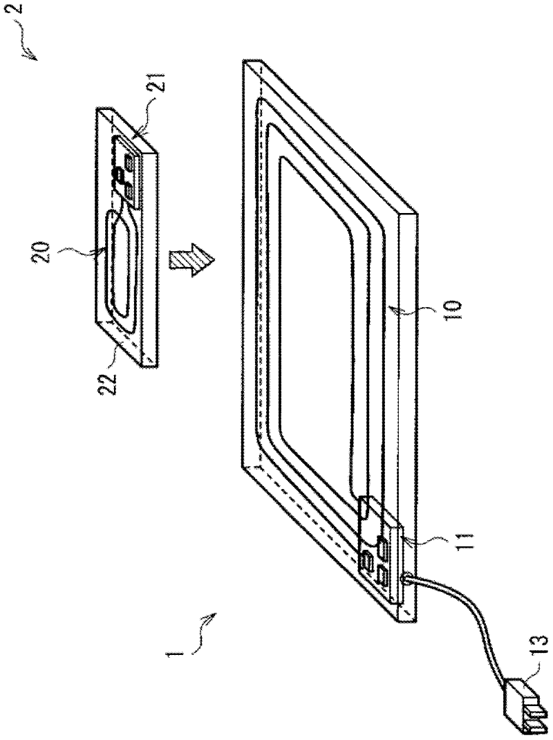
[0037] figure 1 A schematic architecture of a power feeding system according to an embodiment of the present disclosure is shown. The power feeding system includes a charging pad 1 (power feeding device) and a mobile phone 2 (electronic device). The power feeding system is a so-called non-contact type power feeding sy...
example 1
[0075] Figure 7A and 7B are schematic diagrams illustrating the foreign metal detection operation according to Modified Example 1, respectively. The foreign metal detection operation of Modification Example 1 is such that, similar to the foreign metal detection operation of the above-described embodiment, by comparing the amount of change of a predetermined parameter with a predetermined threshold (by performing a comparison with respect to a magnitude relationship), the presence of foreign metal is detected. exists or does not exist. However, in Modified Example 1, even when the surface of the foreign metal X is oxidized, or even when the plating process is performed on the surface of the foreign metal X, detection can be accurately performed.
[0076] Specifically, in Modification Example 1, the detection circuit 21A has a threshold A2 (second threshold) different from the threshold A1 in addition to the threshold A1 (in this case smaller than the threshold A1 ). Thresho...
example 3
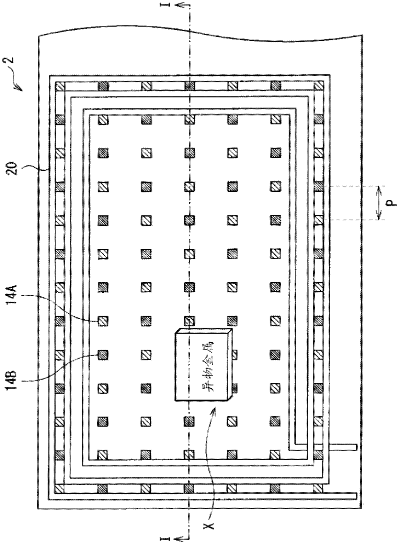
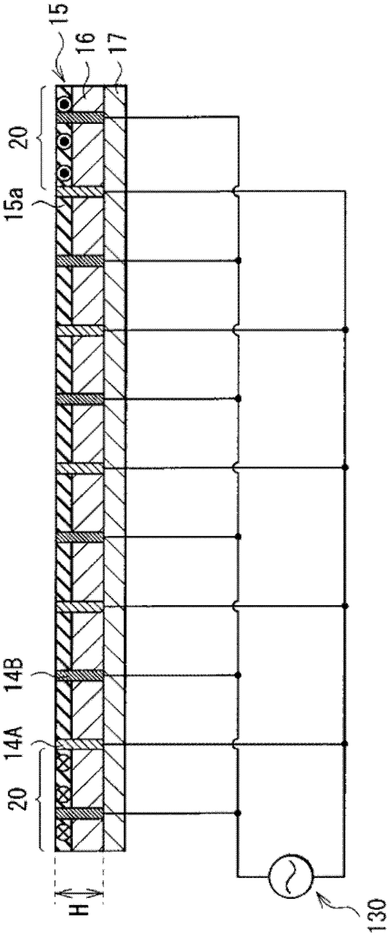
[0096] Figure 10 An example of a planar structure of an electrode pattern according to Modification 3 of the embodiment is shown. In the above-described embodiment, the case where the positive electrode 14A and the negative electrode 14B each have a dot-like shape (needle-like shape as a whole) in plan view is exemplified as an electrode pattern for detecting the foreign metal X. However, the present disclosure is by no means limited to such a dot-like shape, so the electrode pattern may take a linear shape. In this case, it is only necessary that a plurality of positive electrodes 18A1 and a plurality of negative electrodes 18B1 (groups of positive electrodes 18A1 and negative electrodes 18B1 ) are alternately arranged away from each other so as to extend in a direction perpendicular to the extending direction in plan view. However, similarly to the case of the above-described embodiment, it is preferable to provide each of the positive electrode 18A1 and the negative elect...
PUM
 Abstract
Description
Claims
Application Information