Projector and method of controlling projector

A control method and projector technology, applied in the field of projectors, can solve problems such as deformation of projected images and difficulty in detecting movement

Inactive Publication Date: 2012-05-16
SEIKO EPSON CORP
View PDF7 Cites 14 Cited by
  • Summary
  • Abstract
  • Description
  • Claims
  • Application Information

AI Technical Summary

Problems solved by technology

[0004] However, the distortion of the projected image is affected not only by the tilt angle of the projector but also by the projection angle in the horizontal plane, so there is a possibility that the projected image will be deformed when the relative position of the projector relative to the projection surface changes sex
Therefore, in order to cope with the distortion of the projected image during projection, it is desirable to detect the movement of the projector in various directions and the movement to the projection surface side, but it is difficult to detect all the above-mentioned movements with conventional methods.

Method used


Image

  • Projector and method of controlling projector
  • Projector and method of controlling projector
  • Projector and method of controlling projector

Examples


no. 1 approach

[0043] Hereinafter, embodiments of the present invention will be described with reference to the drawings.

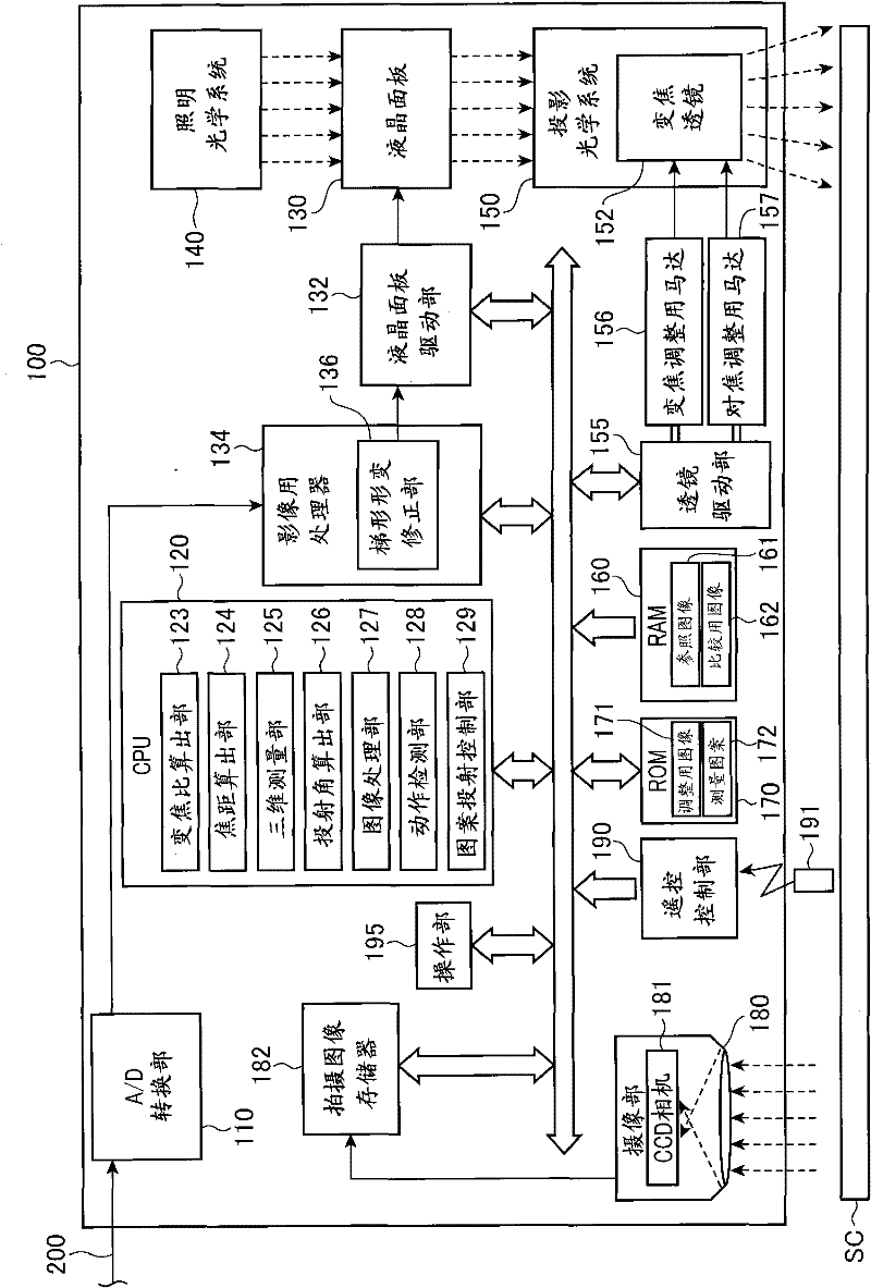
[0044] figure 1 It is a block diagram showing the overall configuration of projector 100 according to the first embodiment. An image signal is input to the projector 100 from an image source (not shown) stored in a built-in storage device, or an external image supply device (not shown) such as a personal computer or various video players. Projector 100 projects light modulated based on an input image signal onto a projection surface such as a screen SC, and displays it as an image (hereinafter referred to as “projected image”). In this embodiment, the screen SC is approximately upright, and the screen surface has a rectangular shape. The image input to the projector 100 may be either a moving image (video) or a still image, and the projector 100 may project a video on the screen SC or continuously project a still image on the screen SC. In the following embodiments, ...

no. 2 approach

[0128] Next, a second embodiment of the present invention will be described with reference to the drawings.

[0129] The projector 100A according to the present embodiment is different from the projector 100 according to the first embodiment in that it does not include the pattern projection control unit 129 .

[0130] Furthermore, the processing performed in projector 100A according to the present embodiment is different from the processing performed in projector 100 according to the first embodiment.

[0131] In the first embodiment described above, the measurement pattern read by the pattern projection control unit 129 is displayed superimposed on the projected image, the imaging unit 180 captures the image while the measurement pattern is projected thereon, and the CPU 120 performs an image capture on the acquired captured image. A process of extracting a measurement pattern is performed.

[0132] On the other hand, in this embodiment, instead of detecting the image of th...


PUM


Abstract

In at least one embodiment of the disclosure, a projector comprises an imaging unit that photographs a projection surface and acquires a first photographed image during a projection of a featured image at a first time point and acquires a second photographed image during the projection of the featured image at a second time point different from the first time point. An image processing unit generates a reference image based on the first photographed image and generates a comparative image based on the second photographed image. A movement detecting unit detects a change in a relative position of the projector with respect to the projection surface by using the reference image and the comparative image generated by the image processing unit.

Description

technical field [0001] The present invention relates to a projector that projects an image on a projection surface, and a control method for the projector. Background technique [0002] It is known that when an image is projected onto a projection surface such as a screen by a projector, the image on the projection surface is distorted depending on the projection angle of the projector. Conventional projectors have a trapezoidal distortion correction function that deforms a projected image so that the image has a correct shape on the projection surface. When the projector moves after performing the trapezoidal distortion correction, the projection angle changes, and the projected image is deformed again. Therefore, conventionally, a technique has been proposed in which a projector having a function of detecting an installation angle performs trapezoidal distortion correction again when a change in the installation angle is detected (for example, refer to Patent Document 1)....

Claims


Application Information

Patent Timeline
Patent Type & Authority Applications(China)
IPC IPC(8): H04N5/74G06T3/00
CPCH04N9/3185H04N9/3194
Inventor 轰晃成
Owner SEIKO EPSON CORP
Why Eureka
Try Eureka