
ventilator

A ventilation fan and air suction port technology, applied in the field of ventilation fans, can solve the problems of large volume, affecting the smoothness of the airflow, and the difficulty of achieving the ideal noise level, and achieve the effect of reducing noise and reducing noise

Active Publication Date: 2015-11-25
PANASONIC ECOLOGY SYSTEMS GUANGDONG CO LTD +1
View PDF2 Cites 0 Cited by
  • Summary
  • Abstract
  • Description
  • Claims
  • Application Information

AI Technical Summary

Problems solved by technology

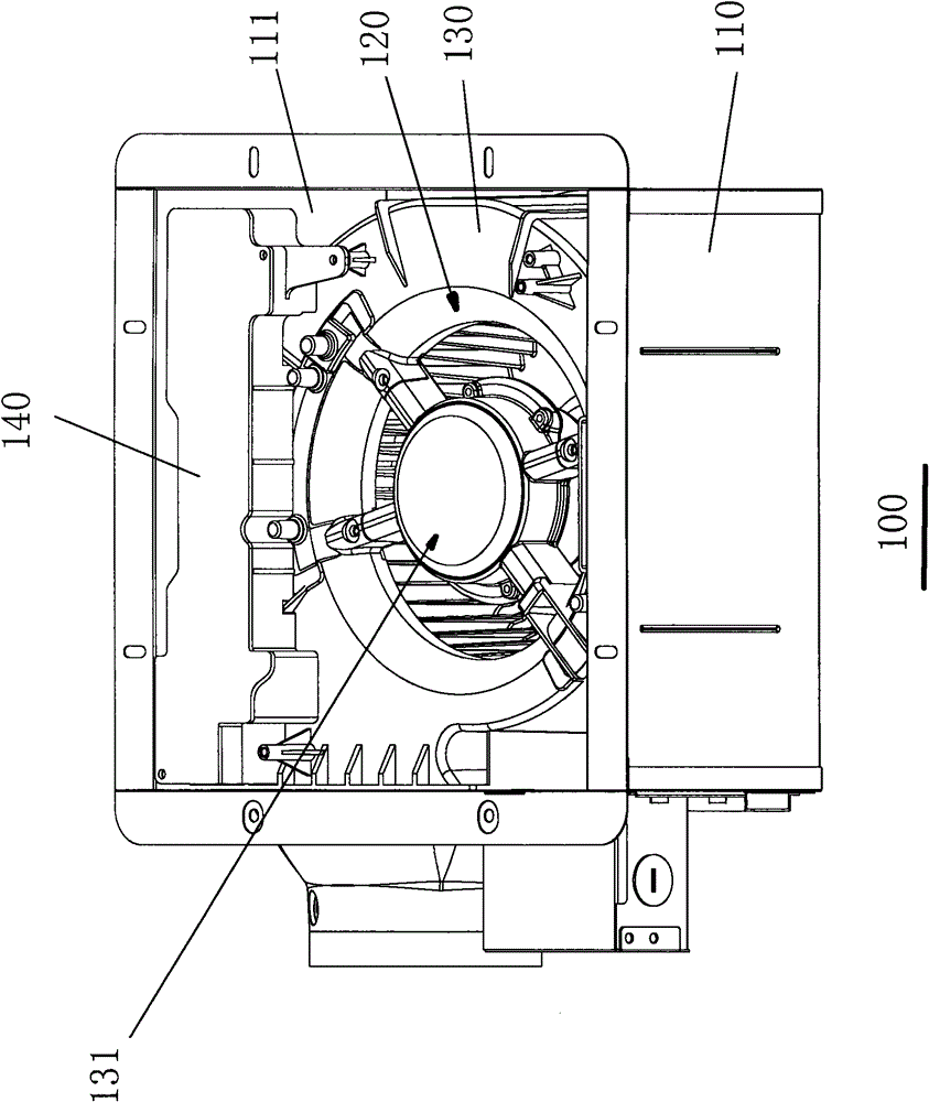
[0003] Since the strip-shaped circuit board box 140 is located on the air suction port 120 side of the ventilation fan snail shell 130 and has a large volume, when the ventilation fan 100 is running, the strip-shaped circuit board box 140 affects the smoothness of the airflow at the suction port. , making it difficult for the noise value to reach the ideal state

Method used


Image

  • ventilator
  • ventilator
  • ventilator

Examples


Embodiment Construction

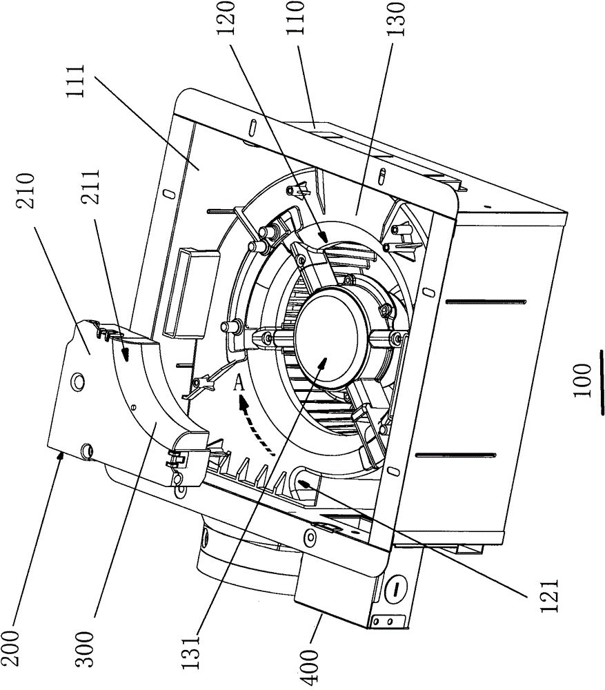
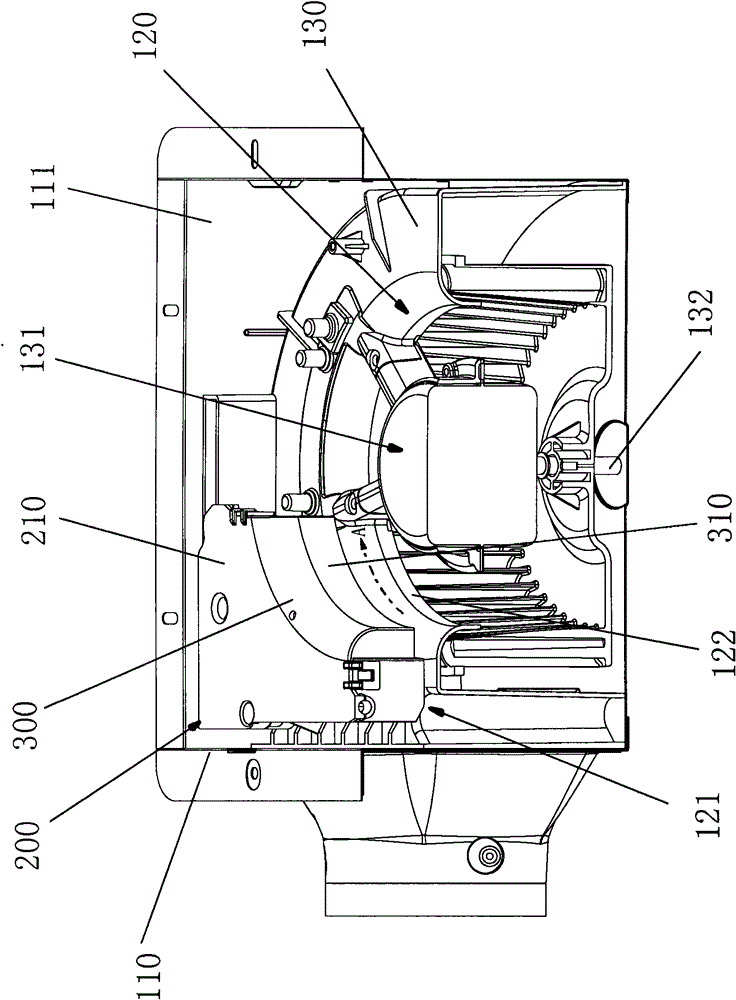
[0017] Figure 2A It is a schematic diagram of the first embodiment of the present invention. Figure 2B It is a schematic cross-sectional view of the first embodiment of the present invention. Such as Figure 2A As shown, the ventilation fan 100 includes: a frame 110 with an opening 111 , a snail shell 130 with an air suction port 120 disposed in the frame 110 , and a fan 131 disposed in the snail shell 130 . Also from the tongue 121 of the snail shell 130 to the direction opposite to the direction of rotation of the blower fan 131 turn 90 degrees (in Figure 2A and Figure 2B , within the range of arrow A rotating clockwise), a circuit board box 200 is fixed on the outer periphery of the air suction port 120 of the ventilator snail shell 130, and the circuit board box 200 is located on one side of the cover 210 on the air suction port side of the snail shell 211 matches the shape of the circumference of the air suction port, that is, after forming an arc-shaped chamfer, ...


PUM


Abstract

The invention relates to a ventilator, which comprises a framework, a snail shell and a fan, wherein the framework is provided with an opening, the snail shell is arranged in the framework and is provided with a wind suction opening, the fan is arranged in the snail shell, a circuit board box is arranged on the snail shell, a silencing plate is fixedly arranged on the outer periphery of the air suction opening of the snail shell of the ventilator, the silencing plate is in a streamline structure formed by using a rotating shaft of the fan as the center through rotating a 90-degree range in the direction opposite to the rotating direction of the fan from a tongue part of the snail shell and then enlarging towards the outside from the air suction opening in the rotating shaft direction of the fan, and the silencing plate has the arc-shaped chamfer shape set to be matched with the circumference of the air suction opening. The ventilator has the advantages that the silencing plate in the streamline structure is arranged in a high static pressure region rotating for 90 degrees in the direction opposite to the rotating direction of the fan from the tongue part of the snail shell, a good noise reduction effect is realized, in addition, the position of the existing circuit board box is changed, the existing circuit board box is changed to a position at the outer side of the silencing plate, and the air flowing of the air suction opening is not blocked, so the noise is further reduced.

Description

technical field [0001] The invention relates to a ventilation fan. Background technique [0002] Such as figure 1 As shown, it is a known ventilation fan 100, including: a frame 110 with an opening 111, a snail shell 130 with an air suction port 120 arranged in the frame 110, a fan 131 arranged in the snail casing 130, and a fan 131 fixed on the ventilation fan snail A strip-shaped circuit board box 140 on the side of the air suction port of the shell 130 . [0003] Since the strip-shaped circuit board box 140 is located on the air suction port 120 side of the ventilation fan snail shell 130 and has a large volume, when the ventilation fan 100 is running, the strip-shaped circuit board box 140 affects the smoothness of the airflow at the suction port. , making it difficult for the noise value to reach the ideal state. Contents of the invention [0004] The object of the present invention is to provide a ventilating fan which operates with low noise. [0005] In order t...

Claims


Application Information

Patent Timeline
Patent Type & Authority Patents(China)
IPC IPC(8): F04D25/08F04D29/66F04D29/42
Inventor 杨敬涛谭谦豪吴炎浓
Owner PANASONIC ECOLOGY SYSTEMS GUANGDONG CO LTD
Learn More