Fan

A fan and fan wheel technology is applied to the components of pumping devices for elastic fluids, non-variable-capacity pumps, pump devices, etc. Improve the effect of heat dissipation

Active Publication Date: 2012-05-23
SUNONWEALTH ELECTRIC MACHINE IND
View PDF5 Cites 5 Cited by
  • Summary
  • Abstract
  • Description
  • Claims
  • Application Information

AI Technical Summary

Problems solved by technology

[0007] However, since the rotor seat 91 and the fan wheel 92 of the existing fan 9 are located in the airflow channel formed between the air inlet 931 and the air outlet 932, the airflow guided by the fan wheel 92 is also easily affected by the fan wheel 92. The obstruction of the rotor seat 91 produces the turbulence phenomenon; moreover, the fan wheel 92 must be assembled with the rotor seat 91 separately, which also causes a lot of inconvenience in assembly and use.

Method used


Image

  • Fan
  • Fan
  • Fan

Examples


Embodiment Construction

[0032] In order to make the above-mentioned and other objects, features and advantages of the present invention more comprehensible, the preferred embodiments of the present invention are specifically cited below, together with the accompanying drawings, as follows:

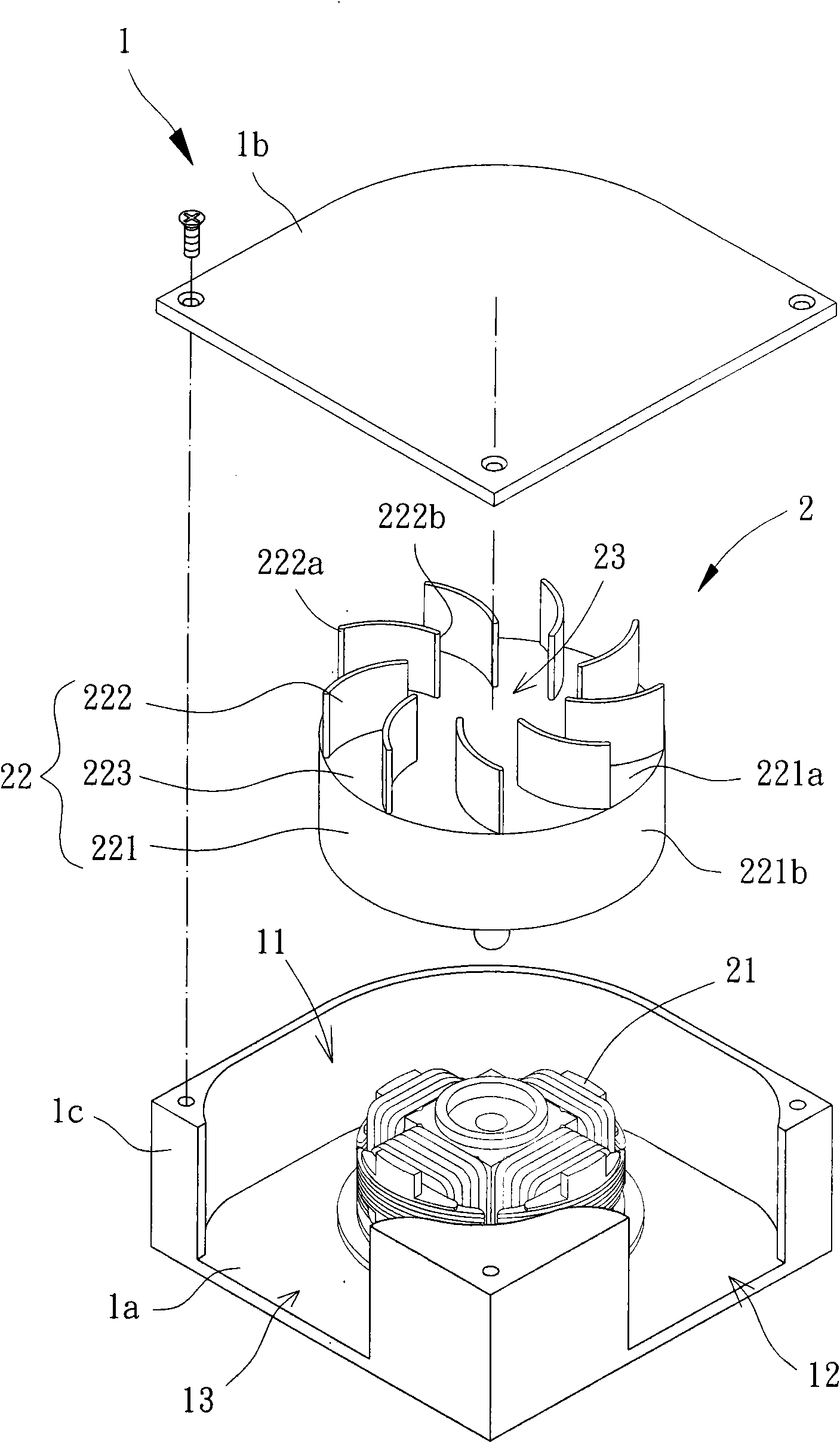
[0033] Please refer to image 3 and 4 As shown, the fan according to the first embodiment of the present invention includes a fan frame 1 and a motor 2 . The fan frame 1 is a frame structure capable of allowing airflow to flow in a radial direction; the motor 2 is combined inside the fan frame 1 .

[0034] The fan frame 1 can be any hollow frame structure capable of accommodating the motor 2 and allowing air flow to be introduced and exported in a radial direction. Wherein the fan frame 1 at least includes a receiving portion 1a, a closing portion 1b and a side wall portion 1c, the receiving portion 1a is spaced opposite to the closing portion 1b, and the side wall portion 1c is located between the receiving po...


PUM


Abstract

The invention discloses a fan, which comprises a fan frame and a motor, wherein an accommodating space is formed inside the fan frame, in addition, the fan frame is provided with at least one side air inlet and at least one side air outlet communicated with the accommodating space, the motor is combined with the accommodating space of the fan frame and comprises a stator and a fan wheel, the fan wheel is rotatablely combined with the stator, the fan wheel is provided with a wheel hub and a plurality of blades, the wheel hub is provided with a top surface, each blade is respectively positioned on the top surface of the wheel hub, each blade respectively comprises a first end and a second end in the radial direction of the fan wheel, the first end and the second end are opposite, the first end of each blade is in outward arrangement, and a flow guide space is formed among the second ends of all blades. Therefore, the occurrence of the turbulent flow phenomenon is effectively prevented, and the heat radiation effect can also be improved.

Description

technical field [0001] The present invention relates to a fan, in particular to a fan capable of introducing and exporting air flow in a radial direction in the radial direction of the fan wheel. Background technique [0002] Existing fans generally include two types: axial flow fans and blower fans. The axial flow fan has an axial air inlet and an axial air outlet opposite to each other in the axial direction, so as to introduce air flow through the axial air inlet, and then export air flow through the axial air outlet, thereby providing heat dissipation; Also, the blower fan has an axial air inlet in the axial direction, and a radial air outlet in the radial direction, so that the airflow is introduced through the axial air inlet, and then exported laterally through the radial air outlet. Airflow, while also having the function of heat dissipation. [0003] However, as far as the axial flow fan is concerned, since it can only guide the airflow toward the axial direction ...

Claims


Application Information

Patent Timeline
IPC IPC(8): F04D25/08F04D29/42F04D29/28
Inventor 洪银树王科鉴陈业丰
Owner SUNONWEALTH ELECTRIC MACHINE IND
Why Eureka
Try Eureka